Free original lessons
Draw a Drum Set: Kit Layout and Hardware Construction
Learn to draw a drum set from overhead layout and front-view construction, with a five-piece arrangement grid and hardware checklist.
Free lesson
Four exercises
Worked answers
Object Drawing Lessons
This lesson teaches you to draw a drum set as a coherent physical object, not a collection of circles. You will plan an overhead kit layout, construct the bass drum and snare in front view, place toms and cymbals on stands, and connect pedal and hardware logically. A defined drawing convention keeps proportions checkable while allowing valid stylistic alternatives. All measurements are hypothetical examples; measure your own equipment if you draw from life.
Practice materials: Printable downloads are not available for this lesson yet. Use the instructions and four exercises below.
Reference illustration
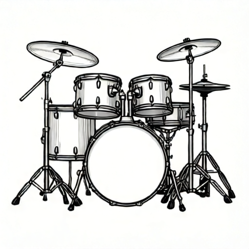
Use the stated measurements and conventions for each exercise.
Plan the overhead kit layout first
Start with a top-down plan because it fixes relationships before perspective complicates them. Draw a rectangle for the drummer's seating zone and a center line from the throne to the bass drum. Place the bass drum on that line, then the snare slightly left of center and closer to the throne. Toms sit above the bass drum in the plan, with the floor tom to the right. Cymbals occupy the outer arc: hi-hat left, ride right, crash between them. Keep stand bases inside the kit footprint so the drawing reads as one object.
Use a simple convention: circles mark drum shells seen from above, short lines mark stand tripods, and small rectangles mark pedal footprints. Label each item once. Check that no stand base overlaps another stand base unless the hardware genuinely shares a clamp; if it does, draw a short connector line.
- Draw the throne rectangle and the center line to the bass drum.
- Place bass drum, snare, toms, floor tom, and cymbal positions as labeled circles.
- Add stand tripods and pedal footprints, keeping bases inside the footprint.
- Check spacing: snare within easy reach of throne, floor tom to the right, hi-hat left.
Construct the bass drum and snare in front view
In front view, the bass drum is a large circle or ellipse with a depth band showing shell thickness. Draw the front hoop, then the shell depth as two short horizontal lines behind the hoop, then the rear hoop partly hidden. Add two legs (spurs) angled outward and a pedal footprint at the bottom center. The snare is a shallower cylinder on a stand: draw the top hoop as an ellipse, the shell depth as a narrow band, and three stand legs meeting at a collar below the shell.
Keep proportions consistent with your overhead plan. If the bass drum diameter is 22 units in the plan, use the same 22 units in front view. Label hypothetical values clearly, for example 'example diameter 22 units', and measure real equipment separately if needed.
- Draw the bass drum front hoop as a circle or ellipse.
- Add shell depth lines and the rear hoop, then spurs and pedal footprint.
- Draw the snare top hoop, narrow shell band, and stand collar with three legs.
- Compare diameters and depths against the overhead plan for consistency.
Place toms, cymbals, and hardware connections
Rack toms mount above the bass drum on a shared post or on separate stands. Draw the post as a vertical line from the bass drum shell to a T-joint, then short arms to each tom. Floor tom legs attach directly to the shell and touch the floor at three points. Cymbal stands are vertical rods with a tripod base and a tilted cymbal at the top; the hi-hat stand has two cymbals and a pedal footprint.
Use a hardware-connection checklist: every drum touches a stand, mount, or leg; every cymbal sits on a stand rod; every pedal footprint connects to a drum or hi-hat. Draw connector lines only where hardware actually joins. This prevents floating drums and impossible stands.
- Draw the tom post and arms from the bass drum to each rack tom.
- Add floor tom legs touching the floor at three points.
- Draw cymbal stand rods, tripods, and tilted cymbals; add hi-hat pedal footprint.
- Run the hardware-connection checklist and fix any floating item.
Use a convention and rubric for valid alternatives
Letter styles and line weights vary, so define your convention before drawing. For example: solid outlines for shells, dashed lines for hidden rear hoops, small circles for stand bases, and single labels. X-height is baseline to midline for any lettering; keep labels consistent. The rubric rewards logical connections and consistent proportions, not a single universal arrangement. A left-handed kit or a four-piece kit can score fully if its internal logic is sound.
- Write your convention at the top of the page: line types, label style, unit.
- Apply the convention consistently across plan and front view.
- Self-check against the rubric: layout logic, construction, connections, labeling.
Worked example
A five-piece kit has a bass drum of example diameter 22 units, snare 14 units, two rack toms 10 and 12 units, and a floor tom 16 units. In the overhead plan the bass drum center is at (0,0), snare at (-6,4), rack toms at (-3,-5) and (3,-5), floor tom at (10,6), hi-hat at (-10,2), ride at (12,-2), crash at (6,-8). Draw the plan and front view, then check connections.
Worked answer
Plan: place labeled circles at the given coordinates inside a footprint rectangle; add tripod marks for hi-hat, ride, and crash, a pedal footprint at bass drum bottom center, and a throne rectangle behind the snare. Front view: bass drum circle of 22 units with depth band, spurs, and pedal; snare ellipse of 14 units on a three-leg stand; rack toms on a shared post from the bass drum; floor tom on three legs. Connections: every drum touches a stand, mount, or leg; every cymbal sits on a rod; pedal footprints connect to bass drum and hi-hat.
Why: Coordinates fix relative positions before drawing. Carrying the same unit values into front view keeps proportions consistent. The connection check catches floating items.
Check: Measure each drawn diameter against its labeled unit value; confirm every stand base is inside the footprint; trace each connector line to a real hardware joint.
Four practice exercises
Exercise 1
Using a grid where one square equals one unit, place a bass drum at (0,0) with example diameter 20 units, a snare at (-5,3) with diameter 13 units, and a hi-hat at (-9,1). Describe the overhead plan and state one connection check.
Show answer and check
Draw labeled circles at the three coordinates inside a footprint rectangle; add a hi-hat tripod mark and a bass drum pedal footprint at bottom center. Connection check: the snare must touch a stand collar and the hi-hat must sit on its rod.
Why: Coordinates fix positions; diameters set circle sizes. The check confirms no floating items.
Check: Measure each circle against its unit diameter and trace one connector line per item.
Exercise 2
A front-view bass drum has example diameter 24 units and shell depth 8 units. Draw it with front hoop, depth band, rear hoop, two spurs, and a pedal footprint. State how you show hidden depth.
Show answer and check
Draw a 24-unit circle for the front hoop, two horizontal depth lines 8 units apart behind it, a partly hidden rear hoop, spurs angled outward, and a pedal footprint at bottom center. Hidden depth is shown with dashed lines for the rear hoop.
Why: Depth band separates front and rear hoops; dashed lines follow the stated convention for hidden edges.
Check: Confirm the depth band measures 8 units and that dashed lines are used only for hidden rear hoops.
Exercise 3
Place two rack toms above a bass drum on a shared post, a floor tom to the right on three legs, and a ride cymbal on a tripod stand to the right. Describe the connector lines you draw and run the hardware-connection checklist.
Show answer and check
Draw a vertical post from the bass drum shell to a T-joint, short arms to each tom, three floor tom legs touching the floor, and a ride stand rod with tripod and tilted cymbal. Connector lines join post to bass drum, arms to toms, legs to floor tom, and rod to tripod. Checklist: every item touches hardware; no floating drums or cymbals.
Why: Shared post reduces stand count; connector lines show real joints only.
Check: Trace each connector line to a hardware joint and confirm three floor contact points for the floor tom.
Exercise 4
Design a four-piece kit (bass drum, snare, one rack tom, one crash) in overhead plan and front view using a single unit. State your convention and one valid alternative that would still score fully.
Show answer and check
Plan: bass drum at center, snare left-front, rack tom above bass drum, crash on a tripod to the right; front view carries the same unit diameters and shows post, stand, and pedal. Convention: solid outlines, dashed hidden hoops, circles for bases, single labels. Valid alternative: a left-handed mirror layout with the same connection logic scores fully.
Why: A single unit keeps plan and front view consistent; the rubric rewards coherence, not one fixed arrangement.
Check: Measure diameters against the unit, confirm every item connects to hardware, and verify the convention is applied throughout.
Common mistakes
- Drawing drums as floating circles with no stands or mounts. Add a stand, mount, or leg to every drum and cymbal, then draw a connector line where hardware joins.
- Using different diameters for the same drum in plan and front view. Carry one unit value from the plan to the front view and label it as a hypothetical example.
- Placing cymbal stand bases outside the kit footprint so the set looks scattered. Keep tripod bases inside the outer arc and check that each base supports its rod.
- Overlapping stand bases without showing a shared clamp. Either separate the bases or draw a short connector line to show shared hardware.
Self-check rubric
- Overhead plan shows throne, bass drum, snare, toms, floor tom, and cymbals with labels.
- Front view carries consistent unit values from the plan.
- Every drum and cymbal connects to a stand, mount, or leg.
- Pedal footprints are placed and connected logically.
- Convention is stated and applied consistently; valid alternative layouts score fully if internally coherent.
Questions and answers
Do I need perspective to draw a drum set?
No. An overhead plan plus a front view is enough to show layout and construction. Perspective is optional and can be added later.
Can I draw a left-handed kit?
Yes. Mirror the layout and keep the same connection logic. The rubric checks internal consistency, not handedness.
What units should I use?
Use any single unit consistently, such as grid squares. Label numerical values as hypothetical examples and measure real equipment separately.
How many cymbals must I include?
A five-piece kit typically includes hi-hat, ride, and one crash. You may add a second crash if your layout stays coherent.