Free original lessons
Draw a Carpenter Figure: Pose and Tool-Handling Practice
Learn to draw a carpenter figure with clear pose construction and believable tool handling. Includes grip guide, practice tasks, and a drawing panel plan.
Free lesson
Four exercises
Worked answers
Object Drawing Lessons
This lesson teaches you to draw a single carpenter figure using a simple construction sequence and deliberate tool-handling choices. You will build the pose from a baseline and midline, place the body masses, then refine the hands around a tool. The focus is the figure and its grip, not a workplace scene. All measurements are hypothetical examples; measure your own paper and tools. A consistent convention is used: x-height is the distance from baseline to midline, and letter styles may vary. Use the rubric to judge clarity and plausibility, not to match one universal drawing.
Practice materials: Printable downloads are not available for this lesson yet. Use the instructions and four exercises below.
Reference illustration
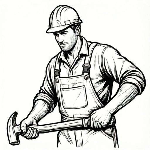
Use the stated measurements and conventions for each exercise.
Pose Construction Sequence
Start with a baseline and a midline. The baseline is the ground contact line; the midline is a vertical guide through the figure. Mark x-height as the distance from baseline to midline. For a standing carpenter, divide the figure into head, torso, and leg units using simple checkable arithmetic. For example, if x-height is 8 units, a hypothetical figure height of 7.5 x-heights is 60 units. Keep units consistent.
Block the pose with three masses: head, ribcage, and pelvis. Add a line for the spine and a line for the tool arm. Decide which hand holds the tool and which hand supports or steadies the work. The pose should read from the silhouette before details are added.
- Draw a baseline and a vertical midline. Mark x-height from baseline to midline.
- Place the head as an oval on the midline; mark the shoulder line and hip line.
- Block the ribcage and pelvis as simple boxes or ovals; connect with a spine curve.
- Draw the tool arm as two segments from shoulder to elbow to wrist; repeat for the support arm.
- Add legs from hip to knee to ankle, keeping feet on or near the baseline.
- Check the silhouette: the tool hand and tool should be readable without facial detail.
Tool-Handling Grip Guide
A believable grip shows contact points. For a hammer, the dominant hand wraps the handle near the end, with the thumb and fingers visible as simple shapes. The support hand may hold a nail or steady a block. For a saw, the dominant hand grips the handle with the index finger along the side; the support hand guides the workpiece. For a plane, both hands contact the body and knob. These are conventions, not universal rules; valid alternatives include different hand dominance or a two-handed grip where plausible.
Draw the tool first as a simple line or rectangle, then wrap the hand around it. Keep the wrist angle consistent with the forearm. Avoid hiding both hands behind the body; show at least one clear contact point.
- Choose one tool and state its orientation: vertical, horizontal, or diagonal.
- Draw the tool as a simple shape with a handle line.
- Place the dominant hand around the handle; mark thumb, finger mass, and wrist.
- Place the support hand on the workpiece or tool body; show contact.
- Check that the tool does not float and that the grip matches the tool's weight and use.
Refining the Figure and Drawing Panel Plan
Refine the figure by adding clothing folds at the elbows and knees, and simple facial features if desired. Keep the tool-handling area uncluttered. A blank panel for drawing a carpenter using a tool is planned as a printable resource; it is not yet built. The panel would provide a framed area and a checklist for pose, grip, and silhouette.
Use the rubric to evaluate clarity, proportion, grip plausibility, and consistency of units. Valid alternatives are accepted when the grip and pose are internally consistent and the tool is clearly held.
- Add clothing folds only where movement occurs: elbows, knees, waist.
- Darken the tool outline and the contact points of the hand.
- Erase construction lines lightly, keeping the midline faint if helpful.
- Label the tool and the dominant hand for your own check.
- Compare the final drawing to the rubric and note one improvement.
Worked example
Construct a standing carpenter holding a hammer vertically in the dominant hand, with the support hand steadying a small block. Use x-height 8 units and a hypothetical figure height of 60 units. Describe the construction and grip.
Worked answer
Draw a baseline and midline. Mark x-height 8 units. Place the head oval at the top; shoulder line about 2 x-heights below the top; hip line about 4 x-heights from the baseline. Block ribcage and pelvis. Draw the dominant arm from shoulder to elbow to wrist, with the hammer handle vertical. Wrap the dominant hand near the handle end, showing thumb and finger mass. Place the support hand on the block at waist height. Check that the hammer does not float and that the feet contact the baseline. The figure height is 60 units, which is 7.5 x-heights; this is a hypothetical proportion, not a standard.
Four practice exercises
Exercise 1
A carpenter holds a saw horizontally at waist height. The dominant hand grips the handle; the support hand guides a plank. Using x-height 6 units and a hypothetical figure height of 45 units, describe the pose construction and one grip check.
Show answer and check
Baseline and midline; x-height 6 units; figure height 45 units equals 7.5 x-heights. Block head, ribcage, pelvis. Draw the dominant arm to the saw handle at waist height; wrap the hand with the index finger along the side. Place the support hand on the plank. Grip check: the saw handle is not floating and the index finger contact is visible.
Why: The arithmetic is simple: 45 divided by 6 equals 7.5. The pose is built from masses, then the tool is drawn before the hand wraps it. The grip check confirms contact.
Check: Measure x-height on your paper; confirm 7.5 x-heights equals your figure height. Trace the saw handle to the hand and confirm at least two contact points.
Exercise 2
Draw a carpenter using a plane with both hands on the tool. The tool is diagonal. State a hypothetical x-height of 5 units and a figure height of 35 units. Describe how you would show both hands and check the grip.
Show answer and check
Baseline and midline; x-height 5 units; figure height 35 units equals 7 x-heights. Block the figure leaning slightly forward. Draw the plane diagonally; place the dominant hand on the rear handle and the support hand on the front knob. Show both wrists and finger masses. Grip check: both hands contact the plane and the tool angle matches the forearm lines.
Why: 35 divided by 5 equals 7. The two-hand grip is plausible for a plane. Drawing the tool first makes hand placement checkable.
Check: Confirm the arithmetic 35 divided by 5 equals 7. Check that both hands touch the plane and that neither wrist is broken at an impossible angle.
Exercise 3
A left-handed carpenter holds a hammer diagonally. The support hand holds a nail. Use x-height 7 units and a hypothetical figure height of 49 units. Describe the construction and one valid alternative.
Show answer and check
Baseline and midline; x-height 7 units; figure height 49 units equals 7 x-heights. Block the figure with the left arm as the tool arm. Draw the hammer diagonally; wrap the left hand near the handle end. The right hand holds the nail at chest height. A valid alternative is a right-handed grip if the pose is mirrored consistently.
Why: 49 divided by 7 equals 7. Hand dominance is a convention; mirroring is a valid alternative when the grip and pose remain consistent.
Check: Check the arithmetic and confirm the tool hand matches the stated dominance. For the alternative, confirm the mirror is consistent and the nail hand does not overlap the hammer head.
Exercise 4
Draw a carpenter kneeling on one knee while holding a screwdriver vertically. Use x-height 4 units and a hypothetical figure height of 30 units. Describe the pose and a grip check.
Show answer and check
Baseline and midline; x-height 4 units; figure height 30 units equals 7.5 x-heights. Block the kneeling pose: one knee near the baseline, the other leg forward. Draw the screwdriver vertically in the dominant hand; wrap the hand around the handle with the thumb visible. The support hand steadies a small block. Grip check: the screwdriver is vertical and the hand contact is clear.
Why: 30 divided by 4 equals 7.5. Kneeling changes the leg construction but the mass-building sequence remains. The vertical tool is easy to check against the midline.
Check: Confirm the arithmetic and that the kneeling knee contacts the baseline. Check that the screwdriver is vertical and the thumb contact is visible.
Common mistakes
- Drawing the tool floating beside the hand. Draw the tool first, then wrap the hand around the handle with visible contact points.
- Using inconsistent units for x-height and figure height. State one unit and use simple arithmetic; for example, 8 units x-height and 60 units figure height.
- Hiding both hands behind the body. Rotate the pose slightly or move the support hand to the workpiece so at least one grip is visible.
- Making the grip identical for every tool. Match the grip to the tool: hammer near handle end, saw with index along side, plane with two-hand contact.
Self-check rubric
- Pose reads clearly from the silhouette without facial detail.
- Baseline, midline, and x-height are used consistently with stated units.
- Tool is clearly held with at least one visible contact point.
- Grip matches the chosen tool and hand dominance is consistent.
- Valid alternatives are accepted when internally consistent and plausible.
- Clothing folds appear only at movement points and do not obscure the grip.
Questions and answers
Do I need to draw a full workplace scene?
No. The brief is a single carpenter figure with pose and tool handling. Keep the background blank or minimal.
What is x-height here?
X-height is the distance from baseline to midline. It is a construction convention, not a lettering standard.
Can I choose a different hand dominance?
Yes. Valid alternatives are accepted if the grip and pose remain plausible and the tool is clearly held.
Are the numerical examples real standards?
No. They are hypothetical examples for simple arithmetic. Measure your own paper and tools.