Free original lessons
Disc Golf Disc Drawing: Rim and Flight-Plate Construction
Learn to draw a disc golf disc by building its rim profile and flight plate with clear steps, a worked example, and practice tasks.
Free lesson
Four exercises
Worked answers
Object Drawing Lessons
A disc golf disc drawing can combine a side-view rim profile with a three-quarter view of the flight plate. These are complementary sketches, not a mechanical projection formula: do not convert the side-profile height directly into ellipse offsets. In the three-quarter view, use a page-vertical centerline, keep top and bottom ellipse centers horizontally aligned, and state the chosen projected offset. All measurements are hypothetical drawing choices, not product specifications.
Practice materials: Printable downloads are not available for this lesson yet. Use the instructions and four exercises below.
Reference illustration
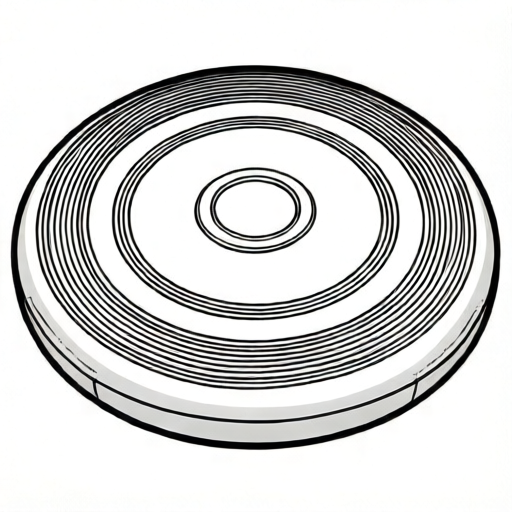
Use the stated measurements and conventions for each exercise.
Set the rim profile as a side-view guide
Begin with a side-view sketch of the rim. Draw a vertical centerline and a horizontal baseline. The rim profile is the curve that runs from the top edge of the flight plate down to the bottom edge of the rim. A common profile is a gentle S-curve: the top edge curves outward, then the lower edge curves inward. Keep the curve smooth and continuous.
Mark three points on the profile: the top edge (where the flight plate meets the rim), the widest point of the rim, and the bottom edge. These points control the rim's thickness and shape. For a hypothetical example, place the top edge 30 mm above the baseline, the widest point 18 mm above the baseline and 5 mm outward from the centerline, and the bottom edge on the baseline. These numbers are only examples; adjust them to your drawing size.
- Draw a vertical centerline and a horizontal baseline.
- Mark the top edge, widest point, and bottom edge on the centerline.
- Connect the points with a smooth S-curve to form the rim profile.
- Check that the curve does not cross itself and that the widest point is between the top and bottom edges.
Wrap the flight plate around the rim
In the three-quarter view, draw the flight plate as an ellipse with a horizontal major axis and a shorter minor axis. Mark its center. Draw the lower ellipse with its center on the same page-vertical centerline; specify its axes and the chosen downward offset separately. This centered construction keeps the left and right sides symmetric.
Connect the visible front edges with a smooth rim band. The side-view profile can suggest whether the rim flares or narrows, but its millimeter values do not set the ellipse separation. Treat the projected ellipse dimensions and the side-profile dimensions as separate hypothetical drawing choices. Measure the left and right bands in the finished sketch and compare them; do not assume either equals the center offset.
- Draw a top flight-plate ellipse with the major axis horizontal.
- Mark its center and a page-vertical centerline.
- Draw a smaller bottom ellipse centered on the same vertical line at the chosen downward offset.
- Connect the visible front edges with matching rim contours.
- Check left/right symmetry and record each ellipse's dimensions separately from the side profile.
Shade the edge to show rim thickness
Shading communicates the rim's curvature. Use a consistent light direction, such as from the upper left. The rim band on the right side is in shadow, so shade it with parallel lines that follow the curve. The left side is lighter; leave it mostly unshaded or use light hatching.
The flight plate is usually flat or slightly domed. Add a subtle gradient from the center to the edge to suggest doming. Keep the shading simple: one dark band on the shadowed rim, one light band on the lit rim, and a soft gradient on the plate. Avoid heavy black areas that hide the construction lines.
- Choose a light direction and mark it lightly outside the disc.
- Shade the shadowed rim band with curved hatching.
- Add a soft gradient on the flight plate from center to edge.
- Check that the shading follows the rim profile and does not flatten the disc.
Check proportions and consistency
Compare the three-quarter view with your side profile as a shape reference, not as a shared scale. Check that both ellipse centers lie on the same vertical centerline, that the lower ellipse uses the stated dimensions and offset, and that the left and right rim contours mirror each other. The rim may widen or narrow according to your chosen profile, but the offset alone does not determine the band width.
Use a ruler to compare corresponding left and right gaps in the drawing. They should match within the tolerance you choose for this exercise. Also confirm that the ellipse minor axis is shorter than its major axis; this makes the flight plate read as tilted rather than as a top-down circle.
- Check both ellipse centers lie on one vertical page axis.
- Record the top and bottom ellipse axes and the chosen center offset.
- Compare matching left and right rim gaps for symmetry.
- Check that the side-view profile is labeled as a separate reference, not used as a scale conversion.
Worked example
In a three-quarter view, draw a flight-plate ellipse with major axis 80 mm and minor axis 50 mm. Draw a bottom ellipse with axes 76 mm and 46 mm, centered on the same vertical axis and 8 mm lower. Keep a separate side-view profile whose vertical extent is 30 mm.
Worked answer
Draw the 80 by 50 mm top ellipse and mark its center. Draw the 76 by 46 mm bottom ellipse with the same horizontal center and an 8 mm downward center offset. Connect the front portions with a symmetric rim band. Draw the 30 mm side-profile extent separately; do not scale it to 8 mm or claim the offset equals the rim width.
Why: The ellipses are given as independent projected drawing measurements, while the side profile is a separate view. Aligning their centers and using matching left/right contours makes the three-quarter construction symmetric.
Check: Measure the top and bottom ellipse axes, confirm their centers share a vertical line, and compare left/right rim gaps. Confirm the side profile remains a separate reference and no 30-to-8 scaling claim is made.
Four practice exercises
Exercise 1
Draw a side-view rim guide with top edge 25 mm above its baseline, widest point 15 mm above the baseline and 6 mm outward, and bottom edge on the baseline. Separately draw top and bottom ellipses 70×45 mm and 64×39 mm, centers horizontally aligned, with the bottom center 7 mm lower.
Show answer and check
The side profile spans 25 mm vertically, with its widest point 15 mm above the baseline and 6 mm outward. In the separate view, draw the 70×45 mm top ellipse and the centered 64×39 mm bottom ellipse 7 mm lower. Mirror the left and right rim contours; the band gap is not automatically 7 mm.
Why: The side profile and projected ellipses have separate measurements. The stated center alignment gives left/right symmetry, but the 7 mm center offset is not a band-width formula.
Check: Check 25 mm vertical profile extent, 15 mm widest-point height, 7 mm ellipse-center offset, and equal left/right rim contours.
Exercise 2
Draw a flat-bottom side profile with top at 20 mm, widest point at 12 mm and 4 mm outward, and bottom at 5 mm. Separately draw ellipses 60×40 mm and 56×36 mm with centers aligned and a 6 mm downward offset.
Show answer and check
The side profile extends from 20 mm to 5 mm, a 15 mm vertical span. The bottom ellipse is centered under the top ellipse, is 56×36 mm, and its center is 6 mm lower. Keep the left and right projected bands symmetric.
Why: Subtracting the profile endpoints gives 20−5=15 mm. That side-view span is not converted into the 6 mm projected ellipse offset.
Check: Verify the side profile span is 15 mm and the separate ellipse-center offset is 6 mm. Compare the left and right contours.
Exercise 3
Draw a domed flight plate using a top ellipse 75×48 mm and a bottom ellipse 71×44 mm, with the bottom center 8 mm below the top center on the same vertical axis. Add a subtle center-to-edge gradient.
Show answer and check
Both ellipse centers share a vertical axis. The bottom ellipse is 8 mm lower and smaller by 4 mm on each full axis. Add a light center and slightly darker edge gradient without crossing the rim boundary.
Why: The two ellipse dimensions and center offset are specified independently. A subtle gradient can suggest doming without changing the outline.
Check: Measure the axes and center offset; check left/right symmetry and that the gradient stays inside the flight plate.
Exercise 4
Draw a wide-rim three-quarter view with a top ellipse 90×55 mm and a bottom ellipse 84×49 mm, sharing a vertical centerline, with the bottom center 10 mm lower. State one symmetry check.
Show answer and check
Draw the two centered ellipses and connect their front edges with a visibly wider but mirrored rim band. The side-view profile may be drawn separately as a shape reference.
Why: The axes and offset define the projected ellipse placement, while the wider band is an explicit drawing choice. Keeping the centers aligned preserves left/right symmetry.
Check: Measure corresponding left and right gaps and confirm the centers align; do not equate the 10 mm offset with band width.
Common mistakes
- Drawing the flight plate as a perfect circle instead of an ellipse. Tilt the disc by making the minor axis shorter than the major axis. A circle looks like a top-down view, not a three-quarter view.
- Making the rim band the same width all around. Vary the band width to match the rim profile. The widest point of the profile should correspond to the widest part of the band.
- Shading the entire rim darkly, hiding the profile. Shade only the shadowed side and keep the lit side light. Use hatching that follows the curve.
- Letting the rim profile cross the flight plate ellipse. Align the top edge of the profile with the front of the top ellipse. The profile should sit below the plate, not through it.
- Treating the side-profile height as a formula for the projected ellipse offset or rim width. State the side-view and three-quarter-view measurements separately, then check symmetry directly in the drawing.
Self-check rubric
- Rim profile is a smooth, continuous curve with a clear top edge, widest point, and bottom edge.
- Flight plate is drawn as an ellipse with a shorter minor axis than major axis.
- Projected ellipses have stated dimensions and a chosen center offset; no unsupported conversion from side-profile height to ellipse separation is claimed.
- Shading follows the rim curve and shows thickness without hiding construction lines.
- Left and right rim contours mirror around the page-vertical centerline within the chosen drawing tolerance.
- Valid alternatives are accepted: different rim profiles, ellipse sizes, and shading styles are allowed if the construction checks pass.
Questions and answers
Do I need to use exact measurements?
No. The numbers in this guide are hypothetical examples. Use them as a starting point, then adjust to your drawing size and the look you want.
What if my disc looks too flat?
Increase the offset between the top and bottom ellipses and add a stronger gradient on the flight plate. Also check that the rim band has visible width.
Can I draw the disc from a top-down view instead?
Yes, but this guide focuses on a three-quarter view because it shows the rim profile and flight plate construction. A top-down view hides the rim thickness.
How do I know my drawing is correct?
Use the check steps: rim band widths match, profile edges meet the ellipses, and the minor axis is shorter than the major axis. These checks confirm the construction, not a single universal shape.