Free original lessons
Isometric Stacked Blocks: A Grid-Based Drawing Guide
Learn to draw 3D isometric scenes of stacked blocks on a ground grid, with depth cues, hidden edges, and clear checkpoints for accuracy.
Free lesson
Four exercises
Worked answers
Object Drawing Lessons
Isometric drawing shows three-dimensional forms on a flat page using a simple, consistent grid. In this guide you will learn to draw stacked blocks on an isometric ground grid, distinguish top, side, and front faces, and use depth cues such as hidden edges to make your scene read clearly. The method is checkable: every edge follows one of three grid directions, and every block face has a predictable shape. You will work from a defined convention, not a single universal style, so valid alternatives are allowed where the convention permits. All practice tasks are self-contained and can be solved from the text alone.
Practice materials: Printable downloads are not available for this lesson yet. Use the instructions and four exercises below.
Reference illustration
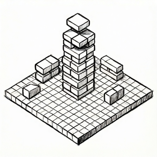
Use the stated measurements and conventions for each exercise.
Setting up the isometric ground grid
An isometric grid uses three axes separated by 120 degrees on the page. In this guide, the convention is: vertical lines run straight up and down; the two ground axes run at 30 degrees above the horizontal, one to the right and one to the left. A ground grid is a lattice of lines parallel to these two ground axes. Each grid intersection is a possible block corner on the ground plane.
Choose a unit length for one block edge along the grid. For example, a hypothetical unit of 20 mm on paper keeps arithmetic simple. Measure your actual paper and tools, then label your chosen value as a hypothetical example. Keep all units consistent: if you use millimetres for the grid, use millimetres for every block edge and height.
Draw the ground grid first. Mark a starting intersection, then step along the right-leaning axis and the left-leaning axis by the same unit. Lightly label a few intersections so you can count positions when stacking blocks. The grid is a guide, not a constraint: you may extend it as needed, but keep the axis directions fixed.
- Draw one vertical reference line and two ground axes at 30 degrees above horizontal, one left and one right.
- Mark equal unit steps along both ground axes from a single origin intersection.
- Complete the lattice by drawing lines parallel to each ground axis through every marked step.
- Label a few intersections with coordinates such as (0,0), (1,0), and (0,1) to support counting.
- Check that every grid line is parallel to one of the two ground axes and that unit steps are equal.
Drawing a single block and its three visible faces
A block is a cube-like form with three visible faces in isometric view: a top face, a left side face, and a right side face. The top face is a rhombus whose edges follow the two ground axes. The left side face is a parallelogram with vertical edges and edges parallel to the left ground axis. The right side face is a parallelogram with vertical edges and edges parallel to the right ground axis.
Start from a ground intersection. Draw the top face first as a rhombus using one unit along each ground axis. From each top corner, drop vertical lines of one unit to form the side faces. Connect the bottom corners to complete the visible outline. In standard isometric view of a single cube, the visible outline does not include the back vertical edge; the hidden edges are the two bottom edges meeting at the hidden back-bottom corner plus the vertical edge rising from that corner to the hidden back-top corner. State your convention for drawing or omitting them, and be able to identify the hidden back-bottom corner.
Depth cues: the top face reads as horizontal because its edges follow the ground axes; the side faces read as vertical because their edges are vertical. Keep line weight consistent so the form does not look tilted. If you draw hidden edges, use a lighter or dashed line and state your convention.
- Mark a ground intersection as the front-bottom corner of the block.
- Draw the top rhombus one unit along each ground axis from the top-front corner.
- Drop vertical lines one unit from each top corner.
- Connect the bottom corners to close the visible side faces.
- Identify the hidden back-bottom corner and its three edges; draw them lightly if your convention includes hidden edges.
Stacking blocks and checking depth cues
Stacking means placing a block directly above another so their vertical edges align. In isometric view, a stack of two blocks shares the same top-face rhombus shape at each level, shifted upward by one unit per level. Draw the lower block first, then draw the upper block from the lower block's top face. Do not shift the upper block sideways unless the arrangement calls for an offset.
For offset stacks, count grid steps along the ground axes before drawing. An offset stack places the upper block on the lower block's top face but shifted by counted grid steps along one ground axis; its base sits on the lower block's top plane, not at ground level. For example, place the second block one unit to the right along the right ground axis on top of the first block's top face. The shared vertical edge helps you check alignment: if the upper block's front-bottom corner sits exactly one counted step from the lower block's top-front corner, the offset is correct.
Depth cues to check: (1) top faces are rhombi, not squares; (2) side faces are parallelograms with vertical edges; (3) hidden edges meet at a single hidden back-bottom corner per block; (4) stacked blocks share vertical edges when aligned. A quick arithmetic check: count the number of visible top faces and compare with the number of blocks not covered from above. If a block is fully covered by another, its top face is hidden.
- Draw the lowest block completely, including its top rhombus.
- For an aligned stack, start the next block at the lower block's top-front corner and repeat the block construction.
- For an offset stack, count grid steps along the ground axes and mark the new front-bottom corner before drawing.
- Check that shared vertical edges align and that each top face is a rhombus.
- Count visible top faces and compare with uncovered blocks; adjust hidden-edge lines according to your stated convention.
Convention, alternatives, and a simple rubric
This guide uses an explicit convention: vertical edges are vertical on the page; ground edges are at 30 degrees above horizontal; one block edge equals one grid unit; hidden edges are optional but must be stated. Labels and annotations are judged for legibility.
Valid alternatives include drawing hidden edges as dashed lines or omitting them entirely, provided the convention is stated. You may also use a different unit length, as long as it is consistent and labelled as a hypothetical example. The rubric rewards consistent axis directions, correct face shapes, aligned stacks, and clear depth cues rather than exact line placement.
- State your convention at the top of your drawing: axis angles, unit length, and hidden-edge treatment.
- Check every edge against the three allowed directions: vertical, left ground axis, right ground axis.
- Check every top face is a rhombus and every side face is a parallelogram with vertical edges.
- Check stacked blocks share vertical edges when aligned and that offsets match counted grid steps.
- Label your unit length as a hypothetical example and keep all measurements in the same unit.
Worked example
Draw an isometric scene on a ground grid with two aligned blocks stacked vertically. Use a hypothetical unit of 20 mm. State your convention and identify the hidden edges.
Worked answer
Convention: vertical edges vertical; ground axes at 30 degrees above horizontal; unit 20 mm; hidden edges dashed. Draw the ground grid with 20 mm steps. Mark a ground intersection as the front-bottom corner of the lower block. Draw the lower block's top rhombus with 20 mm edges along both ground axes, drop 20 mm vertical edges, and close the side faces. Start the upper block at the lower block's top-front corner and repeat the construction with 20 mm edges. The two blocks share vertical edges, so the stack is aligned. Hidden edges: the three dashed edges meeting at each block's hidden back-bottom corner. Check: every top face is a rhombus; every side face is a parallelogram with vertical edges; the upper block's front-bottom corner coincides with the lower block's top-front corner.
Four practice exercises
Exercise 1
On a ground grid with a hypothetical unit of 15 mm, draw one block. State your convention and list the three visible faces.
Show answer and check
A single block with a top rhombus, a left side parallelogram, and a right side parallelogram, all using 15 mm edges. Convention stated, for example: vertical edges vertical; ground axes at 30 degrees above horizontal; hidden edges omitted.
Why: A block has three visible faces in isometric view. The top face uses the two ground axes; the side faces use vertical edges plus one ground axis each. Using one unit for all edges keeps the form consistent.
Check: Verify every edge is vertical or parallel to a ground axis; verify the top face is a rhombus with 15 mm edges; verify side faces have vertical edges of 15 mm.
Exercise 2
Draw two blocks stacked vertically and aligned, using a hypothetical unit of 10 mm. Identify the shared vertical edges and state whether you draw hidden edges.
Show answer and check
Two aligned blocks whose four vertical edges are collinear continuations of the lower block's vertical edges, with the upper block's bottom face coinciding with the lower block's top face. The upper block starts at the lower block's top-front corner. Hidden edges may be dashed or omitted, with the convention stated; if drawn, they meet at each block's hidden back-bottom corner.
Why: An aligned stack places the upper block directly above the lower block, so their vertical edges coincide. Starting at the top-front corner ensures alignment without counting offsets.
Check: Confirm the upper block's front-bottom corner sits on the lower block's top-front corner; confirm shared vertical edges coincide; confirm each top face is a rhombus with 10 mm edges; if hidden edges are drawn, confirm they meet at hidden back-bottom corners.
Exercise 3
Draw two blocks where the upper block sits on the lower block's top face, offset one grid step along the right ground axis from the lower block, using a hypothetical unit of 12 mm. Count the steps before drawing.
Show answer and check
The lower block is drawn first. The offset block sits on the lower block's top face, with its front-bottom corner one 12 mm ground step along the right ground axis from the lower block's top-front corner. Its base is at the lower block's top plane, not at ground level. The offset matches the counted step.
Why: An offset stack requires counting grid steps along a ground axis. Marking the new corner before drawing prevents accidental misalignment and makes the offset checkable.
Check: Measure the offset along the right ground axis between the two blocks' front-bottom corners and confirm it equals one 12 mm step; confirm both blocks use 12 mm edges; confirm top faces are rhombi; confirm the offset block's base is at the lower block's top plane, not at ground level.
Exercise 4
Draw a scene with three blocks: two aligned vertically and a third placed one grid step along the left ground axis away from the viewer from the bottom block, using a hypothetical unit of 8 mm. Count visible top faces and explain your count.
Show answer and check
Two aligned blocks share vertical edges; the third block is offset one 8 mm step along the left ground axis away from the viewer from the bottom block, so it is not under the upper aligned block. Visible top faces: the top of the upper aligned block and the top of the offset block, so two visible top faces, because the bottom aligned block is covered from above.
Why: A block covered from above has a hidden top face. Counting visible top faces checks depth cues and confirms which blocks are covered. The offset is checked by counting one grid step along the left ground axis.
Check: Confirm the aligned pair shares vertical edges; confirm the offset equals one 8 mm step along the left ground axis; count visible top faces and compare with uncovered blocks; confirm all edges follow the three allowed directions; if hidden edges are drawn, confirm they meet at hidden back-bottom corners.
Common mistakes
- Drawing top faces as squares instead of rhombi. Use the two ground axes at 30 degrees above horizontal so the top face has equal unit edges along both axes and reads as a rhombus.
- Shifting an aligned stack sideways without counting grid steps. Start the upper block at the lower block's top-front corner for an aligned stack, or count grid steps along the ground axes before marking an offset.
- Using inconsistent unit lengths for grid steps and block heights. Choose one unit length, label it as a hypothetical example, and use it for every ground step and every vertical block edge.
- Drawing hidden edges in the same weight as visible edges without stating a convention. State whether hidden edges are dashed, lighter, or omitted; keep the chosen treatment consistent across the scene.
Self-check rubric
- Axis directions: all edges are vertical or parallel to one of the two ground axes at 30 degrees above horizontal.
- Face shapes: every visible top face is a rhombus and every visible side face is a parallelogram with vertical edges.
- Stacking: aligned stacks share vertical edges; offset stacks match counted grid steps.
- Depth cues: hidden edges are treated according to a stated convention and meet at hidden back-bottom corners.
- Units: one consistent unit length is used and labelled as a hypothetical example.
- Clarity: any labels or annotations are legible.
Questions and answers
What makes a drawing isometric rather than perspective?
Isometric drawings use three fixed axis directions with no vanishing points. Parallel edges stay parallel on the page, and equal lengths along an axis remain equal. Perspective drawings converge parallel edges toward vanishing points.
Do I have to draw hidden edges?
No. Hidden edges are optional. If you draw them, state your convention, such as dashed lines. If you omit them, you should still be able to identify the hidden back-bottom corner of each block.
How do I check that a stack is aligned?
Check that the upper block's front-bottom corner sits exactly on the lower block's top-front corner and that their vertical edges coincide. For offsets, count grid steps along the ground axes and confirm the new corner matches the count.
Can I use a different unit length?
Yes, as long as it is consistent and labelled as a hypothetical example. Measure your actual paper and tools, then keep every ground step and vertical edge in the same unit.