Free original lessons
Scale Drawing a Bass Guitar Headstock with Tuner Layout
Learn to measure, scale, and redraw a bass headstock with accurate tuner placement using a defined convention and checkable arithmetic.
Free lesson
Four exercises
Worked answers
Object Drawing Lessons
This lesson teaches a repeatable method for drawing a bass guitar headstock to scale, focusing on outline proportion and tuner-hole placement. You will define a drawing convention, measure a reference headstock or use given hypothetical dimensions, convert to a chosen scale, and verify spacing with simple arithmetic. The approach works for any bass headstock shape because it relies on measured relationships rather than a single template. All numerical examples are hypothetical and should be replaced by measurements from your actual reference object or drawing. The goal is a clean, checkable drawing that another person can interpret without guessing.
Practice materials: Printable downloads are not available for this lesson yet. Use the instructions and four exercises below.
Reference illustration
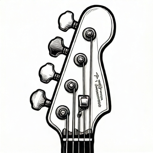
Use the stated measurements and conventions for each exercise.
Define the drawing convention before you draw
A scale drawing needs an explicit convention so that proportions and positions are unambiguous. State the scale as a ratio, such as 1:1 or 1:2, and define what each drawn line represents. For this task, use the convention that the baseline is the lowest point of the headstock outline in the drawing orientation, and the midline is the horizontal centerline of the headstock as measured from the widest left and right outline points. X-height is the vertical distance from baseline to midline. This convention is a choice, not a universal standard; letter styles and headstock shapes vary, so record your convention on the drawing sheet.
Choose units consistently. Millimetres are convenient for instrument hardware because tuner spacing is often in the range of tens of millimetres. If you measure in inches, convert once at the start and label every dimension with the unit. Do not mix units within one drawing. Label the scale ratio and the unit near the title block area of your sheet.
Tuner placement is defined by hole centers, not by the visible tuner buttons. Mark each hole center with a small cross and label it T1, T2, T3, and T4 from the nut end toward the headstock tip. Record the distance from the baseline to each hole center and the distance from the midline to each hole center. These two coordinates fully locate each tuner hole under the convention.
- Write the scale ratio and unit at the top of the sheet.
- Mark the baseline and midline on the drawing area.
- Label the nut end and headstock tip so orientation is fixed.
- Record the convention statement: baseline is lowest outline point; midline is horizontal centerline; x-height is baseline to midline.
Measure the reference and convert to scale
Measure the actual headstock outline at its widest points and at the nut end. Record overall length from nut face to tip, maximum width, and the distance from baseline to midline. If you are using a printed plate with dimension callouts, treat those callouts as the reference measurements and note that they are hypothetical examples for practice. Measure tuner-hole centers from the same baseline and midline so all coordinates share one origin.
Convert every measurement by the scale factor. For a 1:2 scale, divide each real measurement by 2. For 1:1, copy the measurement directly. Keep a conversion table on the sheet: real value, scale factor, drawn value. This table is your arithmetic check and prevents silent unit errors.
Round drawn values to the nearest half millimetre only after conversion, and note the rounding rule. If a converted value is 17.25 mm, drawing it as 17.5 mm is acceptable if you state the rule. Do not round before converting, because that compounds error.
- Measure overall length, maximum width, and baseline-to-midline distance.
- Measure each tuner-hole center as baseline distance and midline distance.
- Divide each measurement by the scale factor and record the drawn value.
- Apply and state a rounding rule, such as nearest half millimetre.
Draw the outline and place tuner holes
Draw the outline first using the converted length and width. Use light construction lines for the baseline, midline, nut line, and tip line. Sketch the curved outline through measured control points rather than guessing a smooth curve. Check symmetry only if the reference is symmetric; many bass headstocks are asymmetric, so do not force mirror symmetry.
Place tuner holes by coordinate. From the baseline, measure upward the converted baseline distance for each hole and mark a short horizontal tick. From the midline, measure left or right the converted midline distance and mark a short vertical tick. The intersection is the hole center. Draw a small circle at the center with a diameter equal to the converted hole diameter, and label it T1 through T4.
Verify spacing arithmetic. For holes in a line parallel to the baseline, the center-to-center spacing should equal the difference between consecutive baseline distances. For holes offset from the midline, check that the sum of left and right offsets equals the total width at that height if the outline is straight there. Record these checks beside the drawing.
- Draw baseline, midline, nut line, and tip line as light construction lines.
- Plot outline control points from converted measurements and connect them smoothly.
- For each tuner hole, mark baseline distance and midline offset, then draw the hole circle.
- Label holes T1 to T4 and write the spacing check arithmetic on the sheet.
Annotate, check, and present the drawing
Annotate the drawing with the scale ratio, unit, convention statement, and a dimension table. Add leader lines to overall length, maximum width, and each tuner-hole coordinate. Keep annotations outside the outline where possible so the shape remains readable.
Run three checks before calling the drawing complete. First, arithmetic check: recompute each converted value from the real value and scale factor. Second, coordinate check: confirm each hole center lies at the intersection of its two measured offsets. Third, proportion check: compare the drawn length-to-width ratio with the real ratio; they should match within your stated rounding rule.
Present the sheet with the drawing, conversion table, and check notes on one page. A second person should be able to reproduce the drawing from your table alone. If they cannot, add the missing measurement or clarify the convention.
- Add scale ratio, unit, convention statement, and dimension table.
- Recompute converted values and compare with drawn values.
- Confirm each tuner hole sits at its two-offset intersection.
- Compare drawn length-to-width ratio with the real ratio and note any rounding difference.
Worked example
A hypothetical bass headstock has overall length 220 mm, maximum width 90 mm, and baseline-to-midline distance 45 mm. Four tuner holes have baseline distances 30, 60, 90, and 120 mm and midline offsets 20, 25, 30, and 35 mm to the right. Draw at 1:2 scale and state the converted values and one spacing check.
Worked answer
Converted values at 1:2: length 110 mm, width 45 mm, baseline-to-midline 22.5 mm. Tuner baseline distances: 15, 30, 45, 60 mm. Midline offsets: 10, 12.5, 15, 17.5 mm. Spacing check: consecutive baseline differences are 15, 15, 15 mm, so center-to-center vertical spacing is 15 mm for all adjacent holes. Draw baseline and midline, plot the outline to 110 mm by 45 mm, mark each hole at its two converted offsets, and label T1 to T4.
Four practice exercises
Exercise 1
A hypothetical headstock has overall length 200 mm and maximum width 80 mm. Draw at 1:2 scale. State the drawn length and width, and compute the drawn length-to-width ratio.
Show answer and check
Drawn length 100 mm, drawn width 40 mm, ratio 100:40 or 2.5:1.
Why: Divide each real measurement by the scale factor 2. The ratio is computed from drawn values and should equal the real ratio 200:80, which is also 2.5:1.
Check: Recompute 200 divided by 2 equals 100 and 80 divided by 2 equals 40. Confirm 100 divided by 40 equals 2.5 and 200 divided by 80 equals 2.5.
Exercise 2
Four tuner holes have baseline distances 25, 50, 75, and 100 mm at 1:1 scale. What is the center-to-center spacing between adjacent holes, and what is the total baseline span from T1 to T4?
Show answer and check
Adjacent spacing is 25 mm; total baseline span from T1 to T4 is 75 mm.
Why: Subtract consecutive baseline distances: 50 minus 25 equals 25, 75 minus 50 equals 25, 100 minus 75 equals 25. The total span is 100 minus 25 equals 75 mm.
Check: Add the three adjacent spacings: 25 plus 25 plus 25 equals 75 mm, matching the total span.
Exercise 3
At 1:2 scale, a tuner hole has a real baseline distance of 70 mm and a real midline offset of 18 mm to the left. State the drawn baseline distance and drawn midline offset, and describe where the hole center is marked relative to the baseline and midline.
Show answer and check
Drawn baseline distance 35 mm; drawn midline offset 9 mm to the left. Mark the center 35 mm above the baseline and 9 mm left of the midline.
Why: Divide both real values by 2. The direction left is preserved because the offset is measured from the midline.
Check: Multiply drawn values by 2: 35 times 2 equals 70 mm and 9 times 2 equals 18 mm, matching the real values.
Exercise 4
A hypothetical headstock has maximum width 96 mm and baseline-to-midline distance 48 mm. Two tuner holes are at midline offsets 24 mm left and 24 mm right at the same baseline distance. At 1:1 scale, what is the horizontal distance between the two hole centers, and does it equal the maximum width? Explain.
Show answer and check
Horizontal distance between centers is 48 mm. It does not equal the maximum width of 96 mm; it equals half the maximum width because each hole is 24 mm from the midline and 24 plus 24 equals 48 mm.
Why: Add the absolute offsets: 24 plus 24 equals 48 mm. The maximum width is the full outline width, while the hole centers are inset from the edges.
Check: Confirm 48 mm is half of 96 mm, and confirm each center is 24 mm from the midline by subtracting 24 from 48 to get 24 mm remaining to the outline edge on each side.
Common mistakes
- Measuring tuner positions from the outline edge instead of a fixed baseline and midline. Use one origin for all coordinates: baseline for vertical distance and midline for horizontal offset. Record both for every hole.
- Converting to scale before measuring all reference values, then mixing converted and real numbers. Complete the real measurement table first, then convert every value in one pass and label the table columns clearly.
- Assuming the headstock is symmetric and mirroring tuner holes. Measure each hole independently. Many bass headstocks are asymmetric; symmetry must be measured, not assumed.
- Rounding each converted value early and accumulating spacing error. Convert first, then apply one stated rounding rule at the end. Check center-to-center spacing against the difference of converted baseline distances.
Self-check rubric
- Scale ratio and unit are stated on the sheet and applied consistently.
- Baseline, midline, and x-height convention are defined and marked.
- Outline length and width match converted reference values within the stated rounding rule.
- Each tuner hole center is located by both baseline distance and midline offset and labeled T1 to T4.
- Conversion table and at least one arithmetic spacing check are shown.
- Drawing is readable, annotations do not obscure the outline, and valid alternative conventions are acceptable if clearly recorded.
Questions and answers
What scale should I use for a bass headstock drawing?
Use 1:1 if the headstock fits your paper, or 1:2 to halve all measurements. State the ratio and unit on the sheet. The choice is yours as long as it is recorded and applied consistently.
How do I define x-height for this drawing?
Under this lesson's convention, x-height is the vertical distance from the baseline to the midline. The baseline is the lowest outline point in the drawing orientation, and the midline is the horizontal centerline from the widest left and right outline points. Record this convention on your sheet because letter styles and headstock shapes vary.
Do I need to draw the tuner buttons?
No. Tuner placement is defined by hole centers. Draw hole circles and label centers T1 to T4. Buttons can be sketched lightly if desired but are not required for the scale check.
How can I check my tuner spacing without special tools?
Use arithmetic. For holes in a line, center-to-center spacing equals the difference between consecutive baseline distances. For offset holes, confirm each center lies at the intersection of its baseline distance and midline offset. Compare drawn values with your conversion table.