Free original lessons
Sharecropper Drawing: Figure, Hoe, Rows and Cabin Backdrop
Learn to draw a sharecropper with a hoe, receding field rows and a simple cabin backdrop using clear proportion, placement and perspective checks.
Free lesson
Four exercises
Worked answers
Object Drawing Lessons
This lesson teaches a single, repeatable approach to drawing a sharecropper figure holding a hoe in front of field rows and a cabin backdrop. You will establish a stable pose, place the hoe so it reads as a working tool rather than a prop, set field rows in simple perspective, and build a cabin that supports the scene without competing with the figure. Line quality is judged by a simple convention: construction lines stay light, and final contour lines are confident and continuous. All numerical values below are hypothetical examples chosen for practice; measure your own paper and tools rather than assuming any standard.
Practice materials: Printable downloads are not available for this lesson yet. Use the instructions and four exercises below.
Reference illustration
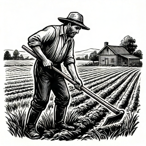
Use the stated measurements and conventions for each exercise.
Establishing the figure and pose
Begin with a light construction line for the ground the figure stands on. Mark a vertical axis for the body and decide the total figure height in your chosen unit, for example 12 units from the ground line to the top of the head. Divide that height into head units: a common practice proportion is about seven to eight head units for an adult figure, but treat this as a guide and adjust to the pose you want. Place the shoulders about one and a half head units below the top of the head, the waist about three head units down, and the knees about six head units down. These are hypothetical example values; check them against your own drawing by measuring with a ruler or a marked strip of paper.
The sharecropper pose should read as active but grounded. Set the feet slightly apart, with the weight mostly on the back leg and the front foot angled toward the hoe. Turn the torso a little toward the tool so the shoulders are not perfectly square to the viewer. Keep the head level or slightly down, as if the worker is looking at the row being tended. Draw the arms after the torso: the forward arm reaches toward the hoe handle, and the back arm bends at the elbow to support the grip. Use simple cylinders for limbs at this stage, then refine the silhouette once the proportions check out.
- Draw a light ground line and a vertical body axis.
- Mark total figure height and divide it into head units for proportion checks.
- Block the torso, hips and legs with simple shapes, keeping the weight on the back leg.
- Add the arms reaching toward the hoe handle, then refine the silhouette.
Placing the hoe so it reads as a working tool
The hoe should connect clearly to the hands and to the ground. Decide the handle length first: a hypothetical example is about two-thirds of the figure height, but measure your own drawing and adjust so the tool looks usable. Draw the handle as a straight line from the upper hand down to the blade, then add the blade as a simple angled shape at the lower end. The blade should touch or nearly touch the ground line, because a hoe that floats weakens the pose. Check that the handle passes through both hands and that the lower hand is not hidden behind the body.
Angle the hoe so it points toward the field rows rather than across them. If the rows recede toward a vanishing area, the hoe can lean slightly in that direction to suggest work along the row. Keep the blade shape simple: a short rectangle or trapezoid is enough at this stage. Avoid adding detailed hardware or invented manufacturing features; the goal is a readable tool, not a product drawing. Measure the handle and blade with a ruler and label any chosen lengths as hypothetical examples in your notes.
- Draw the handle as a straight line from the upper hand to the ground.
- Add a simple blade shape at the lower end, touching or nearly touching the ground line.
- Check that both hands connect to the handle and that the lower hand is visible.
- Angle the hoe toward the field rows and simplify the blade to a readable shape.
Field rows in simple perspective
Field rows give the scene depth. Start with a horizon line across the upper part of the page, then choose a vanishing area on that line. Draw two or three rows as lines that converge toward the vanishing area. Space the rows wider near the bottom of the page and closer together as they recede. A hypothetical example: if the nearest row gap is 3 cm at the bottom edge, the next gap might be 2 cm, then 1.5 cm, then 1 cm, but these are practice values only. Measure your own spacing and keep the units consistent.
Place the figure so the feet sit between two rows rather than on top of a row line. The hoe blade can rest near a row to suggest cultivation. Add a few short cross-marks along the rows to indicate soil or plants, but keep them sparse so the figure remains the focus. Check the perspective by extending the row lines lightly with a ruler; they should meet near the vanishing area without crossing each other before that point.
- Draw a horizon line and mark a vanishing area on it.
- Draw two or three row lines converging toward the vanishing area.
- Space rows wider near the bottom and closer as they recede, measuring with a ruler.
- Place the figure between rows and add sparse cross-marks for soil or plants.
Cabin backdrop construction
The cabin should sit behind the figure and support the setting without dominating it. Place the cabin on the horizon line or slightly below it, off to one side so it does not overlap the figure's head. Block the cabin as a simple box: a rectangle for the wall, a triangle or trapezoid for the roof, and a small rectangle for a door. A hypothetical example is a cabin width about one-third of the figure height, but measure your own drawing and adjust. Keep the roofline simple and avoid invented architectural standards.
Use the same vanishing area to keep the cabin consistent with the field rows. Treat the vanishing area as a region on the horizon line toward which depth lines converge; vertical edges stay vertical, while horizontal depth lines converge toward that area. If you choose to use a single vanishing point, keep it consistent with the rows. The cabin's base should sit below the horizon line, on the ground plane behind the figure, so the cabin reads as standing on the ground rather than floating at eye level; the horizon line passes behind the cabin. Its vertical edges should stay vertical. Add one or two small windows as simple rectangles if needed, but do not overdetail. Check the cabin by comparing its height to the figure: if the cabin looks taller than the figure at the same distance, reduce it or move it farther back. Label any chosen dimensions as hypothetical examples and measure the actual paper and tools you use.
- Place the cabin below the horizon line, off to one side of the figure, so its base sits on the ground plane behind the figure.
- Block the wall as a rectangle, the roof as a simple triangle or trapezoid, and the door as a small rectangle.
- Keep vertical edges vertical and align the cabin's depth lines with the same vanishing area as the rows.
- Compare cabin height to figure height and adjust size or distance as needed.
Worked example
A learner draws a figure 12 cm tall on a 20 cm by 28 cm sheet. The horizon line is 8 cm from the top. The learner places the cabin base 2 cm below the horizon line, draws two row lines converging to a vanishing area 4 cm from the right edge, and sets the hoe handle from the upper hand to the ground. The cabin is drawn 5 cm tall. Check the cabin height against the figure and state one adjustment.
Worked answer
A cabin under half the figure height is acceptable for a backdrop at a distance. Half of 12 cm is 6 cm, so the 5 cm cabin passes the size check and no height reduction is needed. Check that the cabin base sits below the horizon line on the ground plane and that the row lines meet near the vanishing point without crossing earlier. If the cabin appears too large in the drawing, reduce it to about 4 cm or move it farther back; these are hypothetical example values, so measure your own sheet and adjust.
Four practice exercises
Exercise 1
On a sheet with a horizon line 7 cm from the top, draw a figure 10 cm tall standing between two field rows. Place the hoe handle from the upper hand to the ground and make the blade touch the ground line. Describe where the cabin base should sit relative to the horizon line and give one size check.
Show answer and check
The cabin base should sit below the horizon line, on the ground plane behind the figure, off to one side of the figure. A size check is to compare cabin height to the 10 cm figure height; the cabin should be smaller at the same apparent distance. Hypothetical example: a cabin 4 cm tall is acceptable if its base sits below the horizon line.
Why: The horizon line fixes the backdrop position, and comparing cabin height to figure height keeps the scene readable. The hoe blade must touch the ground so the tool reads as working.
Check: Measure the figure height and cabin height with a ruler. Confirm the hoe blade touches the ground line and the cabin base is below the horizon line, not on it.
Exercise 2
Draw three field rows converging to a vanishing area. The nearest row gap at the bottom edge is 3 cm. Choose two smaller gaps for the next rows and state them. Check that the row lines do not cross before the vanishing area.
Show answer and check
Hypothetical example gaps: 3 cm, 2 cm and 1.5 cm. The row lines should converge toward the vanishing area without crossing earlier. Extend the lines lightly with a ruler to confirm they meet near the vanishing area.
Why: Decreasing gaps suggest depth. The check ensures the perspective is consistent rather than accidental.
Check: Measure each gap at the bottom edge with a ruler. Extend the row lines and confirm they meet near the vanishing area without crossing before that point.
Exercise 3
A figure is 14 cm tall. The learner draws a cabin 8 cm tall with its base below the horizon line. State whether the cabin is too large and give one adjustment. Then state one check for the hoe handle.
Show answer and check
The cabin at 8 cm is more than half the figure height, so it may look too large at the same apparent distance. Reduce it to about 5 cm or move it farther back. These are hypothetical example values. For the hoe handle, check that it passes through both hands and reaches the ground line.
Why: A backdrop should not dominate the figure. Comparing heights gives a simple check. The hoe handle check ensures the tool connects to the pose.
Check: Measure cabin height and figure height with a ruler. Confirm the handle line passes through both hand positions and ends at or near the ground line.
Exercise 4
Draw a sharecropper figure with a hoe, two field rows and a cabin backdrop on a 15 cm by 20 cm sheet. Use a horizon line 6 cm from the top and place the cabin base below it. After drawing, list two rubric checks you would apply and state one valid alternative you would accept.
Show answer and check
Two rubric checks: the hoe blade touches or nearly touches the ground, and the field rows converge without crossing earlier. A valid alternative is a different blade shape, provided it connects to the handle and sits near the ground. Hypothetical example: a blade drawn as a trapezoid instead of a rectangle is acceptable.
Why: The rubric focuses on placement and connection rather than a single universal shape. Accepting valid alternatives keeps the check fair while preserving readability.
Check: Measure the horizon line position and the figure height. Confirm the blade is within 1 cm of the ground line, the cabin base is below the horizon line, and extend the row lines to check convergence.
Common mistakes
- The hoe floats above the ground or does not connect to both hands. Redraw the handle as a straight line from the upper hand to the ground, then place the blade so it touches or nearly touches the ground line. Check both hand positions with a ruler.
- Field rows cross each other before reaching the vanishing area. Extend the row lines lightly with a ruler and adjust their angles so they converge near the vanishing area without crossing earlier. Re-measure spacing at the bottom edge.
- The cabin is larger than the figure at the same apparent distance. Reduce the cabin height or move it farther back along the ground plane below the horizon line. Compare cabin height to figure height using a marked strip of paper.
- The figure's weight is centered on both feet, making the pose stiff. Shift the hips slightly over the back leg and angle the front foot toward the hoe. Check that the head, hips and back foot form a stable vertical line.
Self-check rubric
- Figure height and head-unit divisions are marked and checked with a ruler or marked strip.
- The pose shows weight on the back leg and the front foot angled toward the hoe.
- The hoe handle connects to both hands and the blade touches or nearly touches the ground.
- Field rows converge toward the vanishing area without crossing earlier.
- The cabin base sits below the horizon line on the ground plane, and the cabin is smaller than the figure at the same apparent distance.
- Construction lines are light and final contour lines are confident and continuous, so the figure, hoe, rows and cabin read clearly.
Questions and answers
Do I need to use exact head-unit proportions?
No. Head units are a checking aid. Use them to compare parts of your figure, then adjust to the pose you want. Measure your own drawing rather than assuming a fixed standard.
How many field rows should I draw?
Two or three rows are enough to suggest depth. More rows can clutter the scene. Space them wider near the bottom and closer as they recede, and check with a ruler.
Can the cabin overlap the figure?
It can, but keep the overlap away from the head and hands so the figure stays readable. Placing the cabin off to one side is simpler for a first drawing.
What if my hoe blade shape looks different from the example?
Valid alternatives are accepted if the blade connects to the handle, sits near the ground and reads as a tool. The rubric checks placement and connection, not a single universal blade shape.