Free original lessons
Isometric Column Drawing: Base, Fluted Shaft, and Capital
Learn to construct a classical column in isometric projection using axis grids, ellipse guides, and sequenced steps for base, shaft, and capital.
Free lesson
Four exercises
Worked answers
Object Drawing Lessons
Isometric projection lets you draw a classical column with consistent 30-degree axes and clear circular sections. This lesson sequences the base plinth, fluted shaft, and capital block so each part aligns to the same vertical axis. You will use an isometric grid, label ellipse guides for circular sections, and apply a simple convention for flutes. All measurements are hypothetical examples; measure your own paper and tools. The focus is construction, not architectural history.
Practice materials: Printable downloads are not available for this lesson yet. Use the instructions and four exercises below.
Reference illustration
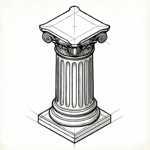
Use the stated measurements and conventions for each exercise.
Set up the isometric axes and grid
Isometric drawing uses three axes: vertical, and two at 30 degrees above horizontal to left and right. On paper, draw a vertical centerline and two 30-degree lines from a common origin. A light grid of parallel lines at these angles keeps edges consistent. Label the vertical axis Z, the left 30-degree axis X, and the right 30-degree axis Y. All column parts share the same Z axis.
Choose a unit length for your drawing, for example 10 mm per grid square. This is a hypothetical example; measure your actual grid spacing and use it consistently. Circular sections in isometric appear as ellipses. Their major axis is perpendicular to the vertical axis and their minor axis is parallel to it. Draw light ellipse guides at the base, shaft top, and capital top before adding detail.
- Draw a vertical centerline and two 30-degree axes from one origin.
- Mark equal grid intervals along each axis using your chosen unit.
- Label Z vertical, X left 30-degree, Y right 30-degree.
- Draw light ellipse guides at planned heights for circular sections.
Construct the base plinth and shaft cylinder
The base plinth is a rectangular block. On the isometric grid, mark its width along X and depth along Y from the centerline, then raise vertical edges to the plinth height. Connect top edges parallel to the base edges. Keep all verticals parallel to Z. The plinth top receives the shaft.
The shaft is a cylinder. Its bottom ellipse sits on the plinth top; its top ellipse sits at the shaft height. Draw both ellipses using the guides, then connect their extreme left and right points with vertical lines. For flutes, define a convention: draw narrow vertical grooves as pairs of short lines spaced evenly around the visible front. Because letter styles and groove spacing vary, any evenly spaced, vertical flute pattern that follows the ellipse curvature is valid.
- Mark plinth width and depth on X and Y axes from the centerline.
- Raise vertical edges to plinth height and connect top edges.
- Draw bottom and top shaft ellipses at chosen heights.
- Connect ellipse extremes with vertical lines to form the cylinder.
- Add evenly spaced vertical flute lines following the visible curvature.
Add the capital block and check alignment
The capital is a block above the shaft. Mark its width and depth on X and Y axes, centered on the same Z axis. Raise vertical edges to the capital height and connect top edges. The capital bottom should meet the shaft top ellipse. Add a simple abacus slab if desired, keeping edges parallel to the isometric axes.
Check that every vertical edge is parallel to Z and every horizontal edge follows X or Y. Ellipse major axes should be perpendicular to Z. Flute lines should be vertical and evenly spaced. Because handwriting and drawing styles vary, accept any consistent convention that preserves these alignments. Measure your actual grid and tools rather than assuming standard tolerances.
- Mark capital width and depth on X and Y axes from the centerline.
- Raise vertical edges to capital height and connect top edges.
- Align capital bottom with shaft top ellipse.
- Verify all verticals parallel Z and horizontals follow X or Y.
- Check ellipse orientation and flute spacing for consistency.
Worked example
Using a grid unit of 10 mm, draw a column with a base plinth 40 mm wide, 30 mm deep, and 10 mm high; a shaft 20 mm diameter and 60 mm high; and a capital 30 mm wide, 30 mm deep, and 15 mm high. Show the isometric axes and one flute convention.
Worked answer
Draw Z vertical and X, Y at 30 degrees. Mark plinth width 4 units along X and depth 3 units along Y from centerline; raise 1 unit for height. Draw shaft bottom ellipse on plinth top with 2-unit diameter; draw top ellipse 6 units above. Connect ellipse extremes with verticals. Mark capital 3 units by 3 units centered on Z, raise 1.5 units. Add evenly spaced vertical flute lines on the visible front. Check all verticals parallel Z and ellipse major axes perpendicular to Z.
Four practice exercises
Exercise 1
A base plinth is 30 mm wide, 20 mm deep, and 10 mm high on a 10 mm grid. Describe how to mark its isometric outline from the centerline.
Show answer and check
Mark 1.5 units along X each side of centerline for width, 1 unit along Y each side for depth, and raise 1 unit vertically. Connect top edges parallel to X and Y.
Why: Width uses the X axis, depth uses Y, and height uses Z. Halving the total width and depth centers the plinth on the vertical axis.
Check: Verify each edge is parallel to X, Y, or Z and that the plinth is centered on the Z axis.
Exercise 2
A shaft has a 20 mm diameter and 50 mm height on a 10 mm grid. Describe the ellipse placement and cylinder sides.
Show answer and check
Draw bottom ellipse with 2-unit diameter at the base top; draw top ellipse 5 units above. Connect extreme left and right points with vertical lines.
Why: The diameter sets the ellipse size, and the height sets the vertical distance between ellipses. Vertical sides connect the widest points.
Check: Confirm both ellipses share the same major axis direction and the sides are parallel to Z.
Exercise 3
A capital is 30 mm wide, 30 mm deep, and 15 mm high on a 10 mm grid. Describe its isometric block and alignment with the shaft top.
Show answer and check
Mark 1.5 units along X and Y each side of centerline, raise 1.5 units vertically, and connect top edges. Align the capital bottom with the shaft top ellipse.
Why: Equal width and depth produce a square plan in isometric. Centering on Z keeps the capital over the shaft.
Check: Check that capital edges follow X, Y, Z and that its center matches the shaft centerline.
Exercise 4
On a 10 mm grid, a column has base 40 by 30 by 10 mm, shaft 20 mm diameter by 60 mm high, and capital 30 by 30 by 15 mm. List three alignment checks after drawing.
Show answer and check
Check all verticals parallel to Z; check ellipse major axes perpendicular to Z; check base, shaft, and capital centered on the same Z axis.
Why: These checks catch tilt, incorrect circular sections, and misalignment between parts.
Check: Use a straightedge along Z and compare ellipse orientations against the grid.
Common mistakes
- Drawing circular sections as true circles instead of ellipses. Use ellipse guides with major axis perpendicular to the vertical axis and minor axis parallel to it.
- Letting vertical edges drift away from the Z axis. Check each vertical edge against the centerline or a parallel grid line before inking.
- Spacing flutes unevenly or letting them cross ellipse edges. Mark equal intervals along the visible front and keep flute lines vertical within the cylinder outline.
- Using inconsistent unit lengths for different parts. Measure your grid spacing once and apply the same unit to base, shaft, and capital.
Self-check rubric
- All vertical edges are parallel to the Z axis.
- Horizontal edges follow the 30-degree X or Y axes.
- Circular sections are drawn as ellipses with major axis perpendicular to Z.
- Base, shaft, and capital are centered on the same vertical axis.
- Flutes are vertical, evenly spaced, and follow the visible curvature.
- Unit length is consistent across all parts.
- Valid alternative conventions for flute spacing and ellipse guides are accepted if alignment rules are met.
Questions and answers
Do I need a special isometric grid?
A light grid of vertical and 30-degree lines is enough. Measure your actual grid spacing and use it consistently.
How many flutes should I draw?
Choose an even number that fits the visible front. Any evenly spaced vertical pattern following the ellipse curvature is valid under the convention.
Can I use a ruler for ellipses?
Yes. Ellipse guides or a ruler with light construction lines both work; keep the major axis perpendicular to the vertical axis.
What if my column looks tilted?
Check that all vertical edges are parallel to Z and that the base and capital are centered on the same Z axis.