Free original lessons
Isometric Stapler Drawing: Hinge and Base Construction
Learn to draw a stapler in isometric projection, building the base, hinge pivot, and upper arm on shared axes with clear steps and checks.
Free lesson
Four exercises
Worked answers
Object Drawing Lessons
Isometric drawing shows three dimensions using lines at 30 degrees to the horizontal, with vertical lines staying vertical. This lesson builds a stapler from an axis box, then adds the base plate, hinge pivot, staple channel, and upper arm. The hinge is the key joint: its pivot must sit on the shared axis line where the upper arm meets the base. You will use a simple convention for line weight and shading, and a rubric that accepts valid alternatives in proportion and detail. All measurements are hypothetical examples; measure your own equipment if you adapt the drawing.
Practice materials: Printable downloads are not available for this lesson yet. Use the instructions and four exercises below.
Reference illustration
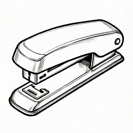
Use the stated measurements and conventions for each exercise.
Set up the isometric axes and axis box
Begin with three axes from a single origin: one vertical, one at 30 degrees up-right, and one at 30 degrees up-left. These represent height, depth, and width. Draw lightly so construction lines can be adjusted.
Enclose the stapler in a light axis box. For a hypothetical stapler, use a base 120 mm long, 40 mm wide, and 25 mm high, with an upper arm rising to 60 mm total height. These numbers are examples only; keep units consistent and label them as hypothetical if you change them.
Mark the hinge line on the shared axis. The hinge pivot sits where the upper arm rotates relative to the base, so its center must lie on the axis line that runs along the length of the stapler. Draw a short vertical tick at the pivot height to locate it.
- Draw the vertical axis and the two 30-degree axes from one origin.
- Mark the base length along the up-right axis and the width along the up-left axis.
- Add verticals at the box corners to the total height.
- Draw the hinge axis line along the length at pivot height and mark the pivot center.
Build the base plate and staple channel
The base plate is a flat slab. On the isometric grid, draw its top face as a parallelogram using the length and width axes, then add vertical edges down to the ground. Keep opposite edges parallel to the axes.
The staple channel sits on top of the base, centered along the length. Draw it as a narrower parallelogram with a small vertical rise. Its centerline should align with the hinge axis line so the upper arm can meet it squarely.
Use a consistent line convention: construction lines light and thin, visible edges medium, and the hinge pivot a small circle with a cross mark. Shading is optional; if used, keep one light source direction and apply it consistently.
- Draw the base top face as a parallelogram on the length and width axes.
- Add vertical edges and the bottom face edges that remain visible.
- Center the staple channel on the base and align its centerline with the hinge axis.
- Mark the hinge pivot as a small circle on the shared axis line.
Add the upper arm and hinge connection
The upper arm is a long block that rises from the hinge and extends over the staple channel. Draw its side profile first on the vertical and length axes, then project the width along the up-left axis.
At the hinge, show the arm meeting the base at the pivot. The pivot circle should sit on the shared axis line, and the arm edges should converge toward it without crossing. A small gap or overlap is acceptable if the pivot remains clearly on the axis.
Finish by checking that all three axis directions are respected: verticals stay vertical, and length and width edges stay at 30 degrees. Erase unnecessary construction lines only after the checks pass.
- Draw the arm side profile from the pivot upward and forward.
- Project the arm width along the up-left axis.
- Connect the arm to the pivot circle on the shared axis line.
- Check axis directions and line weights, then clean up construction lines.
Worked example
Using hypothetical dimensions of base 100 mm by 30 mm by 20 mm and total height 50 mm, describe the first four construction lines for an isometric stapler and state where the hinge pivot goes.
Worked answer
Draw a vertical axis and two 30-degree axes from one origin. Mark 100 mm along the up-right axis for length and 30 mm along the up-left axis for width. Add verticals to 20 mm for the base height, then extend the hinge axis line along the length at 35 mm height and place the pivot center on that line. The pivot sits on the shared axis line so the upper arm can meet the base squarely.
Four practice exercises
Exercise 1
A stapler has a hypothetical base 80 mm long, 24 mm wide, and 16 mm high. The hinge pivot is at 28 mm height on the shared axis. Describe how to place the pivot and the first base edges.
Show answer and check
Draw the three axes from one origin. Mark 80 mm along the up-right axis and 24 mm along the up-left axis. Add verticals to 16 mm for the base. Draw the hinge axis line along the length at 28 mm height and center the pivot circle on it.
Why: The base uses length and width axes with vertical height. The pivot must lie on the shared axis line at the stated height so the arm can connect squarely.
Check: Verify that the base edges are parallel to the 30-degree axes, verticals are vertical, and the pivot center lies on the hinge axis line at 28 mm.
Exercise 2
A drawing shows a staple channel 30 mm wide on a base 24 mm wide. State the error and give a corrected width that is hypothetical and consistent.
Show answer and check
The channel is wider than the base, which is incorrect. A corrected hypothetical channel width is 12 mm, centered on the base.
Why: The staple channel should sit within the base width and be centered along the length. A narrower width keeps the construction valid.
Check: Compare channel and base widths on the same axis; the channel must be smaller and centered.
Exercise 3
Describe how to check that an upper arm is isometric when its side profile is drawn first. Include one numerical check using hypothetical values.
Show answer and check
After drawing the side profile on the vertical and length axes, project the width along the up-left axis. Check that the arm width edges are at 30 degrees and parallel. For example, if the arm width is 18 mm, the projected width on the up-left axis should measure 18 mm along that axis direction.
Why: Isometric projection keeps true lengths along the axes. Projecting the width along the correct axis preserves the isometric convention.
Check: Measure the projected width along the up-left axis and confirm it matches the stated width; confirm all verticals remain vertical.
Exercise 4
A hinge pivot is drawn 5 mm to the right of the shared axis line. Explain why this is a problem and describe the fix using a hypothetical pivot height of 30 mm.
Show answer and check
The pivot is off the shared axis, so the upper arm will not meet the base squarely. Move the pivot center back onto the axis line at 30 mm height and redraw the arm edges to converge on it.
Why: The hinge pivot defines the rotation point between arm and base. Placing it on the shared axis keeps the joint aligned in isometric projection.
Check: Check that the pivot center lies on the hinge axis line at the stated height and that arm edges converge toward it without crossing.
Common mistakes
- Drawing the hinge pivot off the shared axis line. Re-mark the axis line along the stapler length at pivot height and center the pivot circle on it before drawing the arm.
- Using 45-degree lines instead of 30-degree isometric axes. Reset the grid so length and width edges are at 30 degrees to the horizontal; verticals remain vertical.
- Making the staple channel wider than the base. Check the channel width against the base width on the same axis and keep it narrower and centered.
- Inconsistent shading direction on the arm and base. Choose one light source direction and apply the same shading rule to all faces.
Self-check rubric
- Three isometric axes are present and correctly oriented: vertical, 30 degrees up-right, 30 degrees up-left.
- Base plate is drawn as a parallelogram with parallel opposite edges and vertical sides.
- Staple channel is centered and narrower than the base.
- Hinge pivot is a clear mark on the shared axis line where the arm meets the base.
- Upper arm connects to the pivot without crossing edges and respects axis directions.
- Line convention is consistent: construction lines light, visible edges medium, pivot marked.
- Valid alternatives in proportion, detail level, and optional shading are accepted if axis and hinge rules are met.
Questions and answers
Do I need exact millimeter measurements?
No. The numbers here are hypothetical examples. Keep proportions consistent and label any chosen values as examples.
Can the hinge be drawn as a simple circle?
Yes. A small circle with a cross mark on the shared axis line is a valid convention for the pivot.
Is shading required?
No. Shading is optional. If used, keep one light source direction and apply it consistently.
How do I know the drawing is isometric?
Check that verticals are vertical and length and width edges are at 30 degrees to the horizontal.