Free original lessons
Negative Space Robot Drawing: Contour Study with Surrounding Shapes
Learn to draw a robot by defining its silhouette through negative space and surrounding shapes, with joint gaps, antenna spaces, and panel contours.
Free lesson
Four exercises
Worked answers
Object Drawing Lessons
Negative space drawing asks you to see the empty areas around and inside a subject as shapes with their own boundaries. For a robot, this is especially useful because robots combine rigid panels, narrow joints, and thin antennas that are easy to misdraw when you focus only on the outline. In this study, you will use a simple convention: treat every gap between robot parts and every surrounding shape as a closed region, then draw those regions first. The robot emerges as the leftover space. This approach improves proportion, spacing, and contour accuracy without requiring complex construction. All measurements and numerical examples are hypothetical and should be replaced by measurements of your actual paper and tools. The printable resources described here are planned, not yet built; the instructional steps below are self-contained.
Practice materials: Printable downloads are not available for this lesson yet. Use the instructions and four exercises below.
Reference illustration
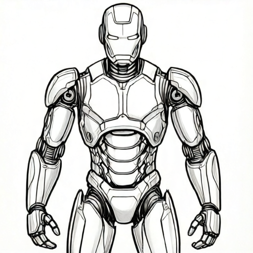
Use the stated measurements and conventions for each exercise.
Defining the Negative-Space Convention
Use a clear convention: the robot silhouette is the positive shape, and every enclosed or surrounding empty region is a negative shape. Draw negative shapes as closed contours before drawing the robot outline. For joints, treat the narrow gap between two robot parts as a thin negative shape. For antennas, treat the space between the antenna and the head as a negative shape. For panel spaces, treat the recessed area inside a panel as a negative shape only if it is visibly enclosed by a contour.
Letter styles and handwriting vary, so this convention does not prescribe a single correct line quality. A valid alternative is to shade the surrounding area instead of outlining negative shapes, as long as the robot silhouette remains identifiable and the negative regions are clearly separated. Use consistent units: measure in millimeters on your actual paper. For example, if your paper is 210 mm by 297 mm, a hypothetical robot plate might occupy a 120 mm by 160 mm area, but measure your own plate.
- Place or imagine a robot silhouette plate on your paper. Measure its actual width and height in millimeters and record them.
- Identify at least three negative regions: one joint gap, one antenna space, and one panel space. Label them lightly.
- Draw the boundary of each negative region as a closed contour, using the same line weight for all negative shapes.
- Check that each negative contour touches the robot silhouette at the correct points without crossing it.
Drawing Surrounding Shapes and Joint Gaps
Surrounding shapes are the areas outside the robot that are bounded by the paper edge or by other objects. Start with the largest surrounding shape, then subdivide it. For a robot, the space between the arm and the torso is often a narrow surrounding shape that changes width along its length. Draw that shape as a tapering contour rather than a uniform gap. Joint gaps should be drawn as thin negative shapes with two parallel or slightly curved edges; the gap width should match your measured or estimated value.
Use simple checkable arithmetic. If a joint gap is 3 mm wide on your reference and your drawing scale is 1:1, the drawn gap should be 3 mm. If you scale the robot to half size, the gap becomes 1.5 mm. Keep units consistent and label any hypothetical values as examples. Do not invent manufacturing tolerances; measure your actual equipment or reference.
- Draw the largest surrounding shape first, then the next largest, working inward toward the robot.
- For each joint gap, draw two edges and close the ends with short curves. Verify the gap width with a ruler.
- For each antenna space, draw the negative shape between the antenna and the head as a closed region.
- Compare the negative shapes to the robot silhouette: if a negative shape looks too wide or too narrow, adjust the robot contour, not the negative shape, to preserve the convention.
Panel Spaces and Contour Consistency
Panel spaces are enclosed negative regions inside the robot, such as the recessed area around a control panel. Draw them only when the panel boundary is visible as a closed contour. If a panel space is open to the surrounding area, treat it as a surrounding shape instead. Keep contour consistency: every negative shape should have a clear inside and outside, and no negative contour should merge with another without a visible boundary.
A useful check is to shade all negative shapes lightly with a pencil. The robot should remain unshaded. If any robot part becomes shaded, the negative contour has crossed the silhouette. This shading check is a valid alternative to outlining and is part of the rubric.
- Identify panel spaces that are fully enclosed by robot contours. Draw each as a closed negative shape.
- Shade all negative shapes lightly, leaving the robot unshaded.
- Inspect the boundary between shaded and unshaded areas: it should match the robot silhouette.
- Erase shading if you prefer outlines, but keep the negative contours visible.
Gap-Identification Guide for Joints, Antenna, and Panels
Use a gap-identification guide to classify each empty region before drawing. Joint gaps are narrow and connect two robot parts. Antenna spaces are elongated and often triangular or curved. Panel spaces are enclosed and roughly rectangular or circular. Surrounding shapes are outside the robot and bounded by the paper edge or other objects. Classify each region, then draw it with the appropriate contour style.
This guide is a reasoning tool, not a universal answer key. Different robot designs will produce different negative shapes. The rubric rewards correct classification and consistent contour treatment, not a single silhouette.
- List every empty region you can see or imagine around and inside the robot.
- Label each region as joint gap, antenna space, panel space, or surrounding shape.
- Draw the regions in order from largest to smallest, checking classification as you go.
- Review the drawing: every labeled region should be visible as a closed contour or shaded area.
Worked example
A robot silhouette is 100 mm tall and 60 mm wide. A joint gap between the upper arm and torso is 4 mm wide at the top and 2 mm wide at the bottom. The antenna space is a triangle with a 10 mm base and 15 mm height. Draw the negative shapes first, then the robot silhouette, using outlines. Check the gap widths with a ruler.
Worked answer
Draw the largest surrounding shape around the 100 mm by 60 mm silhouette. Draw the joint gap as a tapering closed contour 4 mm wide at the top and 2 mm wide at the bottom. Draw the antenna space as a triangle with a 10 mm base and 15 mm height. Then draw the robot silhouette so that it touches these negative contours without crossing them. Check: the joint gap measures 4 mm and 2 mm at the marked points; the antenna triangle measures 10 mm by 15 mm; the robot remains unshaded.
Four practice exercises
Exercise 1
A robot arm has a joint gap that is 5 mm wide at the shoulder and 3 mm wide at the elbow. The arm is drawn at 1:1 scale. Describe how to draw the joint gap as a negative shape and what to check with a ruler.
Show answer and check
Draw a tapering closed contour with one edge 5 mm from the shoulder side and the other edge 3 mm from the elbow side, closing both ends. Check that the gap measures 5 mm at the shoulder and 3 mm at the elbow with a ruler.
Why: The joint gap is a narrow negative shape that changes width along its length. Drawing it as a closed contour with measured widths preserves the convention and makes the gap checkable.
Check: Measure the drawn gap at both marked points. If either measurement differs by more than 1 mm from the stated value, adjust the contour.
Exercise 2
An antenna space is a triangle with a 12 mm base and 18 mm height. The robot head is 30 mm wide. Draw the antenna space first, then describe where the robot head contour should touch the triangle.
Show answer and check
Draw a triangle with a 12 mm base and 18 mm height. The robot head contour should touch the triangle along its base and one side, leaving the triangle as a closed negative shape. The head width of 30 mm is independent and should be checked separately.
Why: The antenna space is an elongated negative shape. Drawing it first defines the gap between antenna and head. The head contour must touch the triangle without crossing it.
Check: Verify the triangle base is 12 mm and height is 18 mm. Confirm the head contour touches the triangle at the base and one side and does not cross the triangle.
Exercise 3
A robot torso has a rectangular panel space 20 mm by 10 mm. The surrounding area outside the robot is bounded by a paper edge 50 mm from the robot. Classify the panel space and the surrounding area, then state the order of drawing.
Show answer and check
The panel space is an enclosed negative shape; the surrounding area is a surrounding shape. Draw the surrounding area first, then the panel space, then the robot silhouette.
Why: Largest negative shapes are drawn first to establish the overall composition. The panel space is smaller and enclosed, so it comes after the surrounding area.
Check: Confirm the panel space is closed and measures 20 mm by 10 mm. Confirm the surrounding area is bounded by the paper edge and does not merge with the panel space.
Exercise 4
A robot drawing uses shading instead of outlines for negative shapes. The robot is 80 mm tall. A joint gap is shaded and measures 2 mm wide. State whether this is valid under the convention and describe one check.
Show answer and check
Yes, shading is a valid alternative if the convention is stated and applied consistently. Check that the robot remains unshaded and that the shaded joint gap is 2 mm wide and clearly separated from other shaded regions.
Why: The convention allows outlining or shading as long as negative regions are clearly separated and the robot silhouette remains identifiable. The 2 mm width is a checkable value.
Check: Measure the shaded gap width and confirm the robot area is unshaded. If the shading crosses the robot silhouette, the drawing is invalid under the convention.
Common mistakes
- Drawing the robot outline first and then adding negative shapes as an afterthought. Draw the largest negative shapes first, then let the robot silhouette emerge from their boundaries.
- Treating all gaps as the same width. Measure or estimate each joint gap separately and draw tapering or varying widths where appropriate.
- Shading the robot instead of the negative space. Keep the robot unshaded and shade only the negative regions, or use outlines consistently for negative shapes.
- Merging two negative shapes without a visible boundary. Close each negative contour separately and check that the boundary between them is visible.
Self-check rubric
- Negative shapes are drawn as closed contours or clearly shaded regions before or alongside the robot silhouette.
- At least one joint gap, one antenna space, and one surrounding shape are identified and drawn.
- Joint gap widths are measured or estimated and labeled with consistent units; hypothetical values are labeled as examples.
- The robot silhouette remains unshaded and identifiable, and no negative contour crosses it.
- Valid alternatives such as shading instead of outlining are accepted if the convention is stated and applied consistently.
Questions and answers
Do I have to outline negative shapes, or can I shade them?
Either is valid under the convention. Outlining and shading are both accepted as long as the robot silhouette remains identifiable and negative regions are clearly separated.
How wide should a joint gap be?
Measure your actual reference or equipment. If you use a hypothetical example, label it as hypothetical. For instance, a 3 mm gap at 1:1 scale becomes 1.5 mm at half scale.
What if my robot has no visible panel spaces?
Then do not invent enclosed panel spaces. Use joint gaps, antenna spaces, and surrounding shapes instead. The convention requires only that you classify and draw the negative regions that exist.
Can I use a different line weight for different negative shapes?
Yes, but keep the convention consistent. If you vary line weight, state the rule you used, such as thicker lines for surrounding shapes and thinner lines for joint gaps.