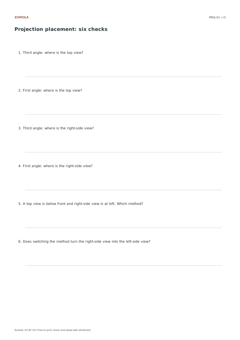
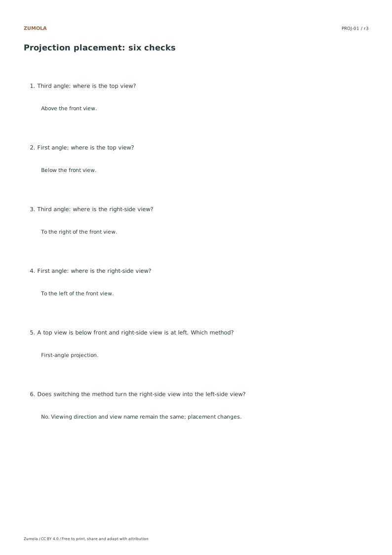
The same front, top and right views can occupy different places on the sheet. Compare both arrangements without changing the object or relabeling its sides.
Same model. Two layouts. 6 questions + answer key.
A printable task with a way to check it
The same front, top and right views can occupy different places on the sheet. Compare both arrangements without changing the object or relabeling its sides.
Choose US Letter or A4, then download the PDF for printing or the SVG for editing. Keep the student worksheet separate from its answer or reference completion. All files, including the answers, are free without signup.
Choose your paper and download
Download paper size
Every worksheet and answer is free. No signup.
Free original resourcePROJ-REF
First and third angle comparison
Original practice with a separate reference answer. Choose Letter or A4.
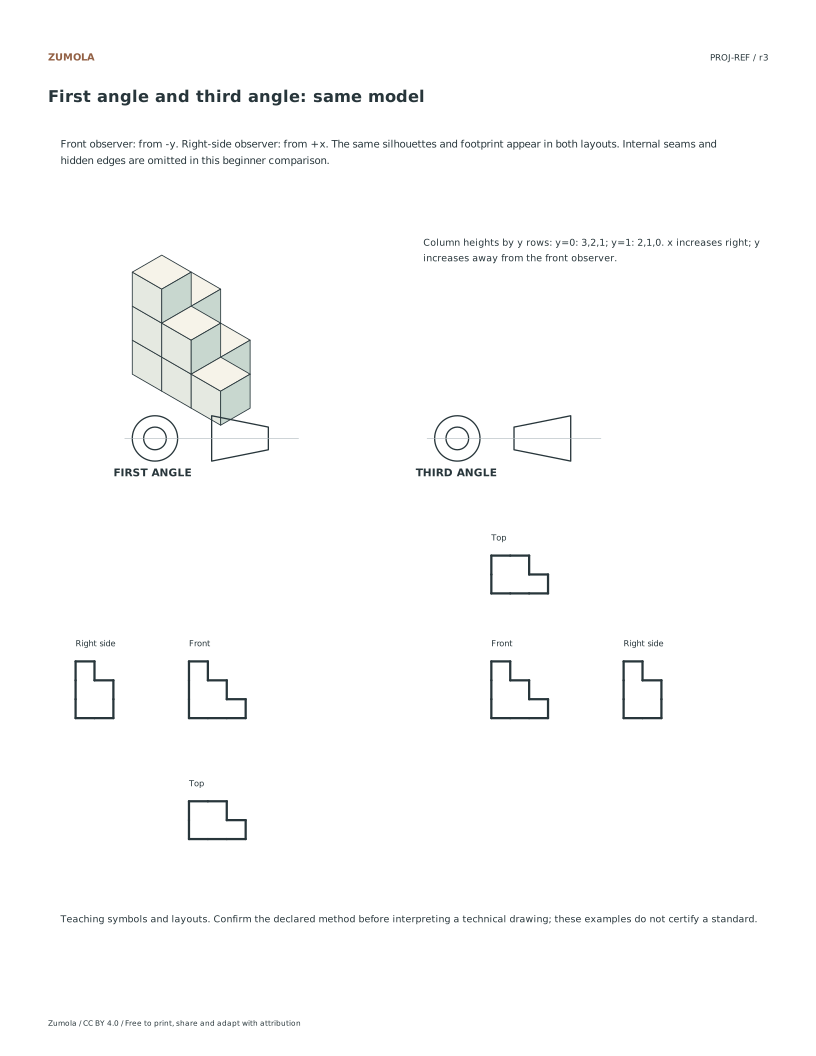
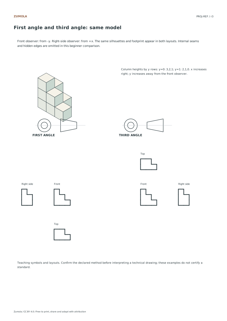
The shared model has column heights [3, 2, 1] in its front row and [2, 1, 0] in its back row. The front observer looks from −y toward +y; the right observer looks from +x toward −x. The front silhouette therefore has heights 3, 2, 1, the right silhouette has heights 3, 2, and the top footprint has five occupied cells. Moving between layouts does not change those results.
Read the original teaching symbols under each arrangement. With concentric circles on the left in both drawings, first angle places the cone’s wide end nearest the circles. Third angle places its narrow end nearest them. Symbols may be encountered in another overall orientation, so identify the relationship of the end view to the tapered side view rather than memorizing “circle left” alone.
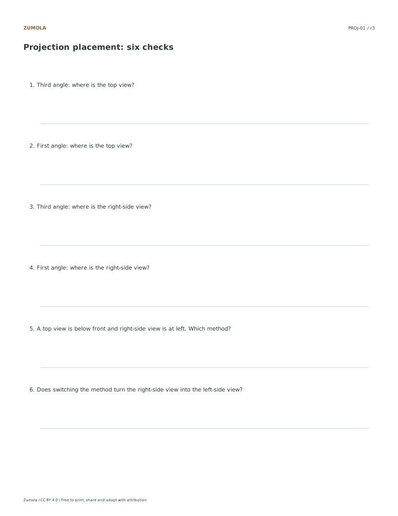
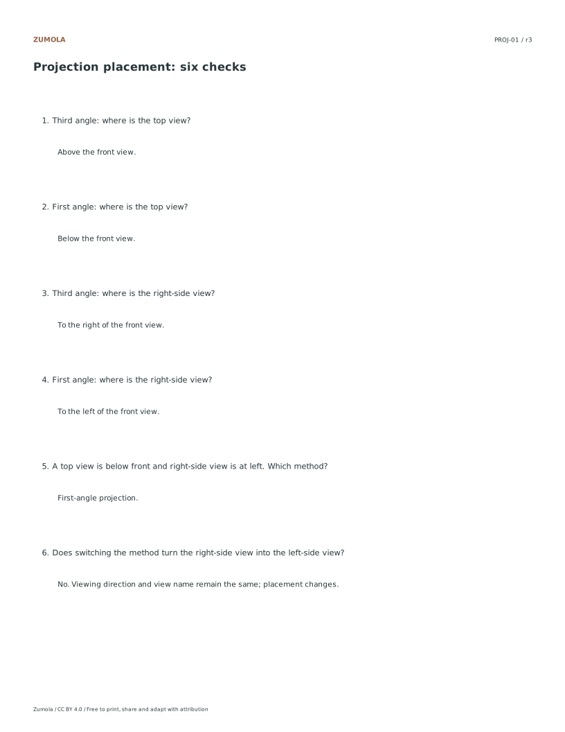
Try the six questions before opening the answer: top placement in each method, right-view placement in each method, whether the right view changes its name when moved, and identification of the method from a described layout. The answer prints each result with its question. These simplified silhouettes and symbols are instructional diagrams; they do not claim ASME or ISO certification.
Work through the page
Understanding View Placement Logic
The core distinction between first and third angle projection lies in how views are arranged relative to the front view. In third angle projection, the top view is placed above the front view, and the right-side view is positioned to the right of the front view. Conversely, first angle projection places the top view below the front view and the right-side view to the left of the front view. This arrangement results from different unfolding methods of the projection planes. The observer looks from negative y to positive y for the front view and from positive x for the right view. Understanding this spatial relationship prevents confusion when interpreting technical drawings.
Interpreting the Projection Symbol
The projection symbol serves as a critical identifier for the projection convention used. In both first and third angle examples, the symbol maintains concentric circles on the left side. The key difference is the orientation of the cone. In first angle projection, the cone has its large end nearest the circles. In third angle projection, the cone has its narrow end nearest the circles. This reversal indicates the viewing direction and plane unfolding method. Recognizing this specific orientation helps users quickly determine the projection type without needing to analyze every view placement in the drawing.
Analyzing Block Height Data
To verify understanding, compare the block heights using the provided data sets. The front view heights are listed as three, two, and one. The right-side view heights are three and two. These values correspond to the same solid object viewed from different directions. When comparing first and third angle layouts, ensure the heights match the specific viewing angles. The front observer looks from negative y to positive y, while the right observer looks from positive x. Consistent height data across views confirms the correct interpretation of the solid geometry despite the different view placements.
Small checks that catch common errors
Watch for
Check instead
Relabeling the left view as the right view in first angle projection.
In first angle projection, the right-side view is placed to the left of the front view. Do not change the label based on position; the view remains the right-side view regardless of its location on the sheet.
Assuming the cone orientation is identical in both projection symbols.
In the two symbols printed here, the concentric circles remain on the left. First angle puts the cone’s wide end next to the circles; third angle puts its narrow end next to them. Read the whole symbol, not just the position of one circle.
Expecting hidden edges or internal seams in silhouette views.
Silhouettes and footprints in these examples omit hidden edges and internal seams. Focus on the visible outer boundaries and height data rather than looking for internal structural lines that are not rendered in these specific views.
Print a test sheet before a full pack
Use the PDF that matches the paper loaded in your printer. Choose Actual size / 100% and turn off Fit, Shrink and browser headers. The SVG keeps millimeter dimensions, but an editor or browser can rescale it; the PDF is the simpler print path. Measure any calibration bars with a separate physical ruler when the exercise depends on printed size. A screen preview does not establish physical scale.
Packs combine the same individual pages; they are not extra different exercises. Print a student copy first and keep references nearby for review. Letter and A4 preserve the stated grid spacing or model definition while their surrounding white space can differ. Color is optional: the references also use line position, text or relative lightness to explain the result.
Useful answers
Does moving a view change its shape?
Changing between these two layouts moves the same front, top and right views. It does not mirror the right view or turn it into a left view. Keep each viewing direction fixed.
How many questions are included in the placement exercise?
The resource includes six placement questions. These are accompanied by a separate answer sheet to facilitate self-checking or grading. The questions focus on distinguishing between first and third angle view arrangements based on the provided geometric data.
Why are some block edges missing?
This activity compares exterior silhouettes and a top footprint. Cube seams and hidden edges are omitted so that view placement stays clear. It is a teaching example rather than a complete manufacturing drawing.
Are the answers and editable files free too?
Yes. Every linked PDF, SVG, worksheet and answer is free without signup. The original Zumola resources use CC BY 4.0: credit Zumola, link the license and indicate changes. Analytics consent is not required to download or use them.
Optional Google Analytics helps us understand which free resources are useful. It is off until you allow it. Drawing tools and downloads work with either choice. Privacy details