Free printable resources · Original practice

Orthographic drawing exercises.
One model, three views.

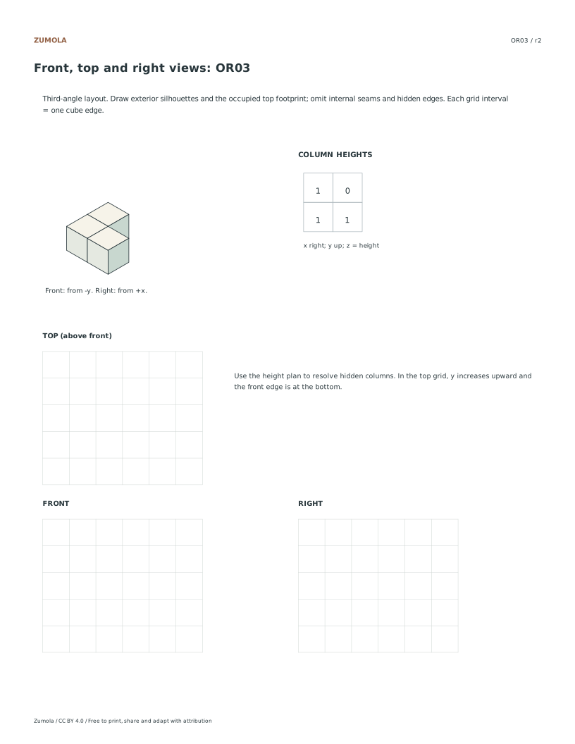
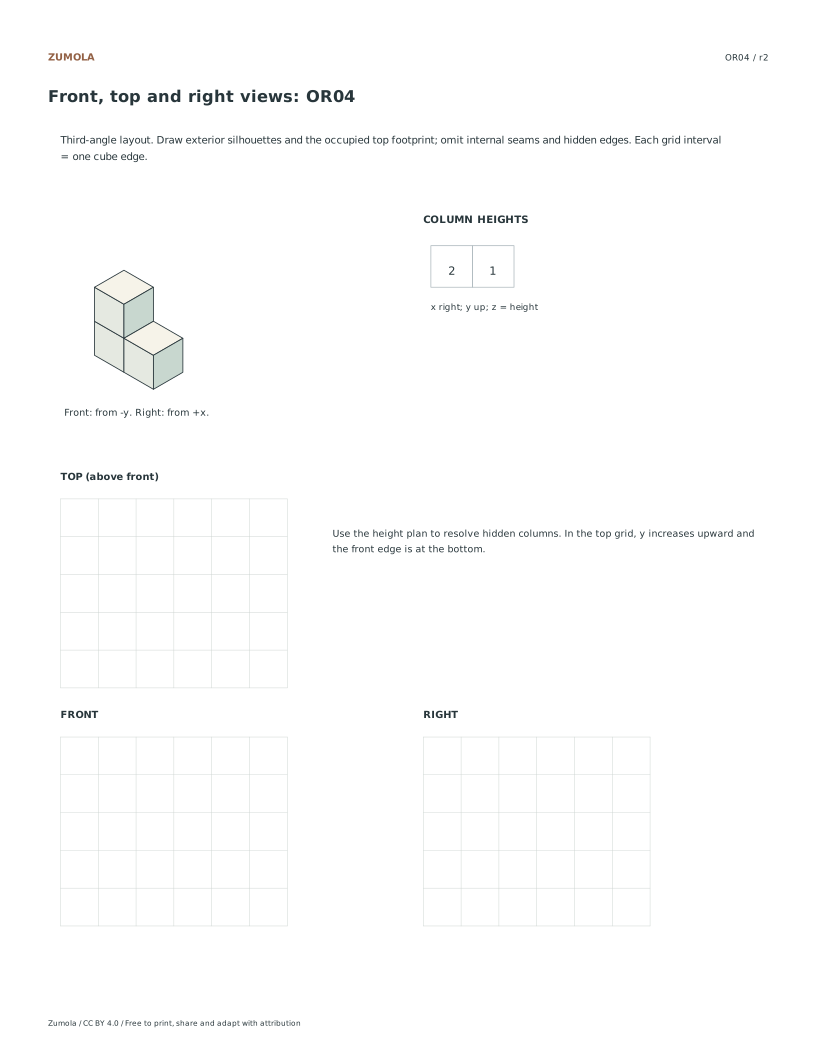
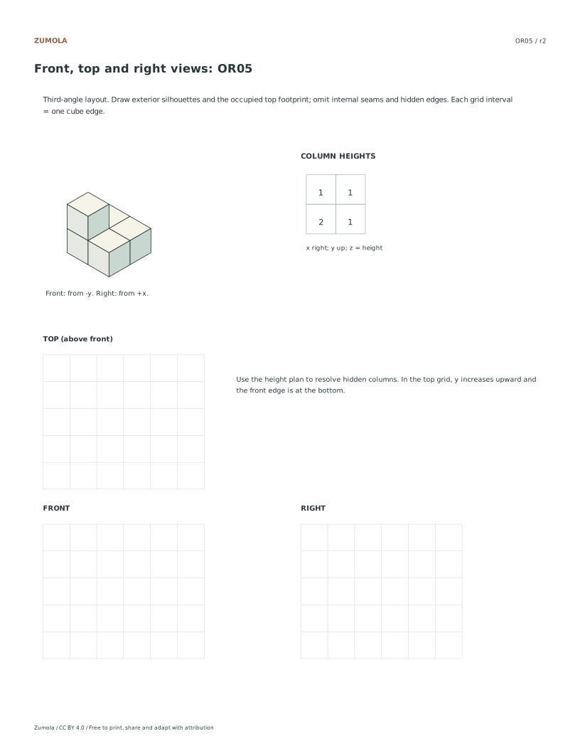
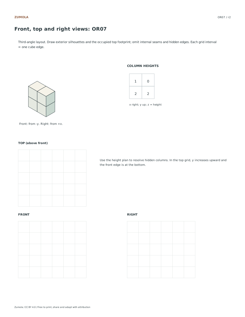
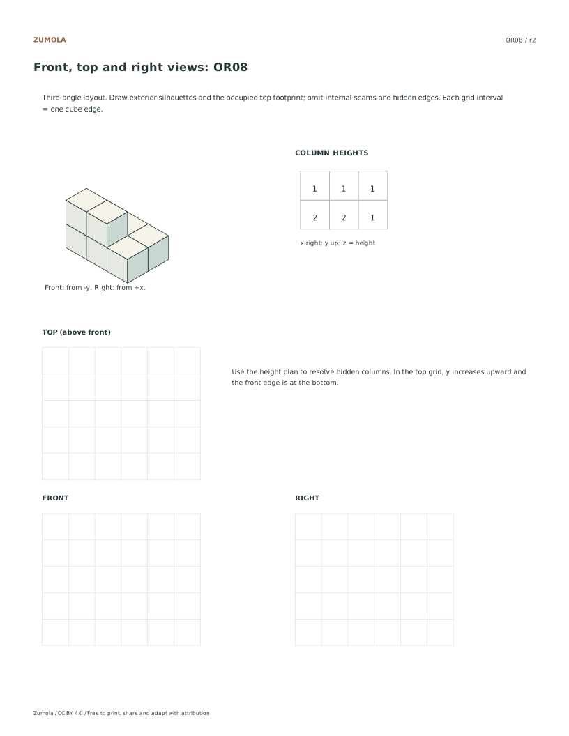
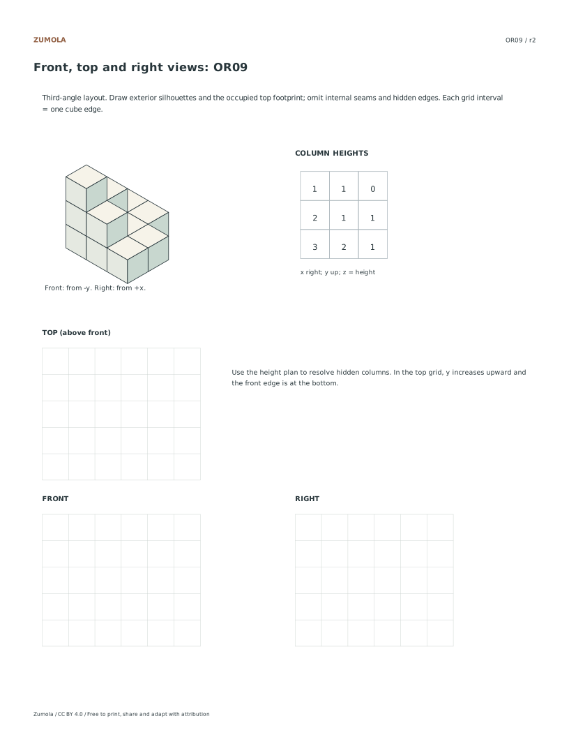
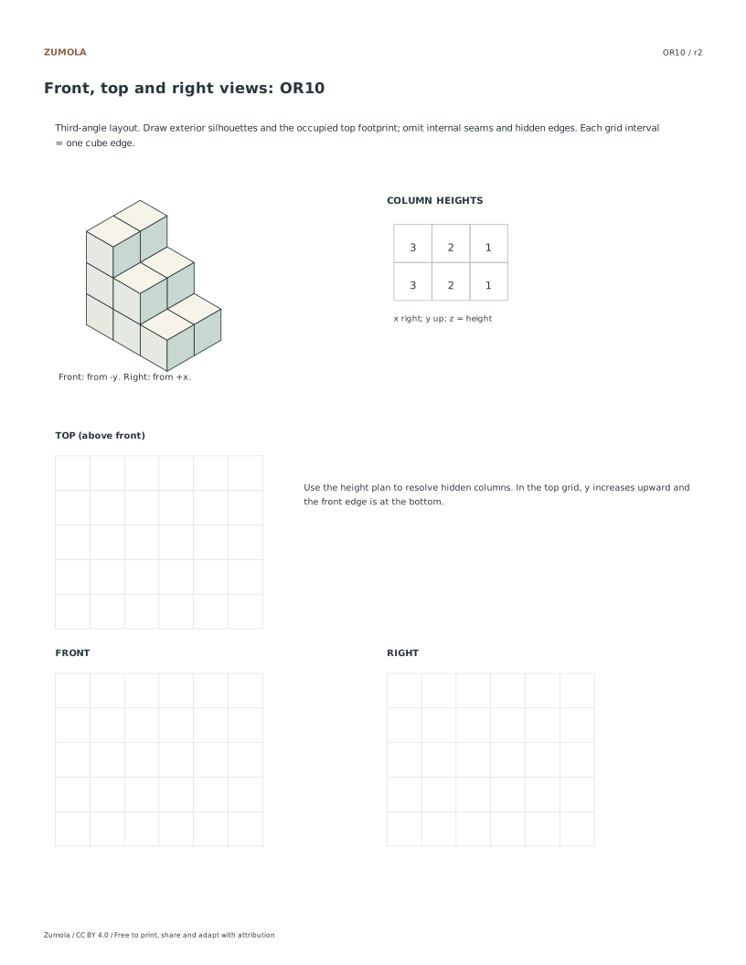
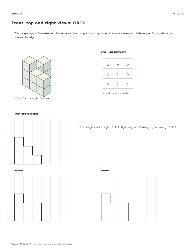
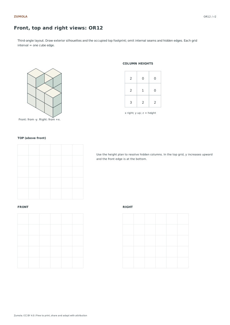
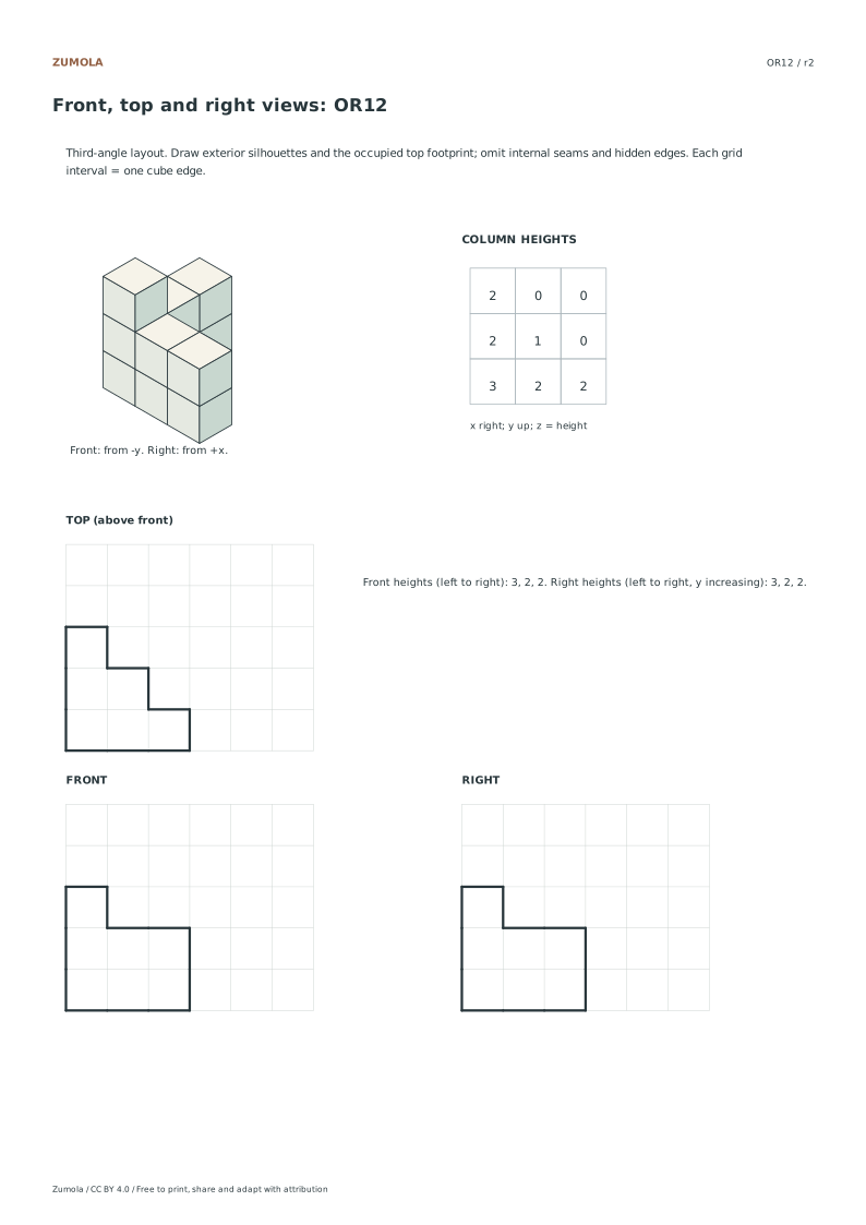
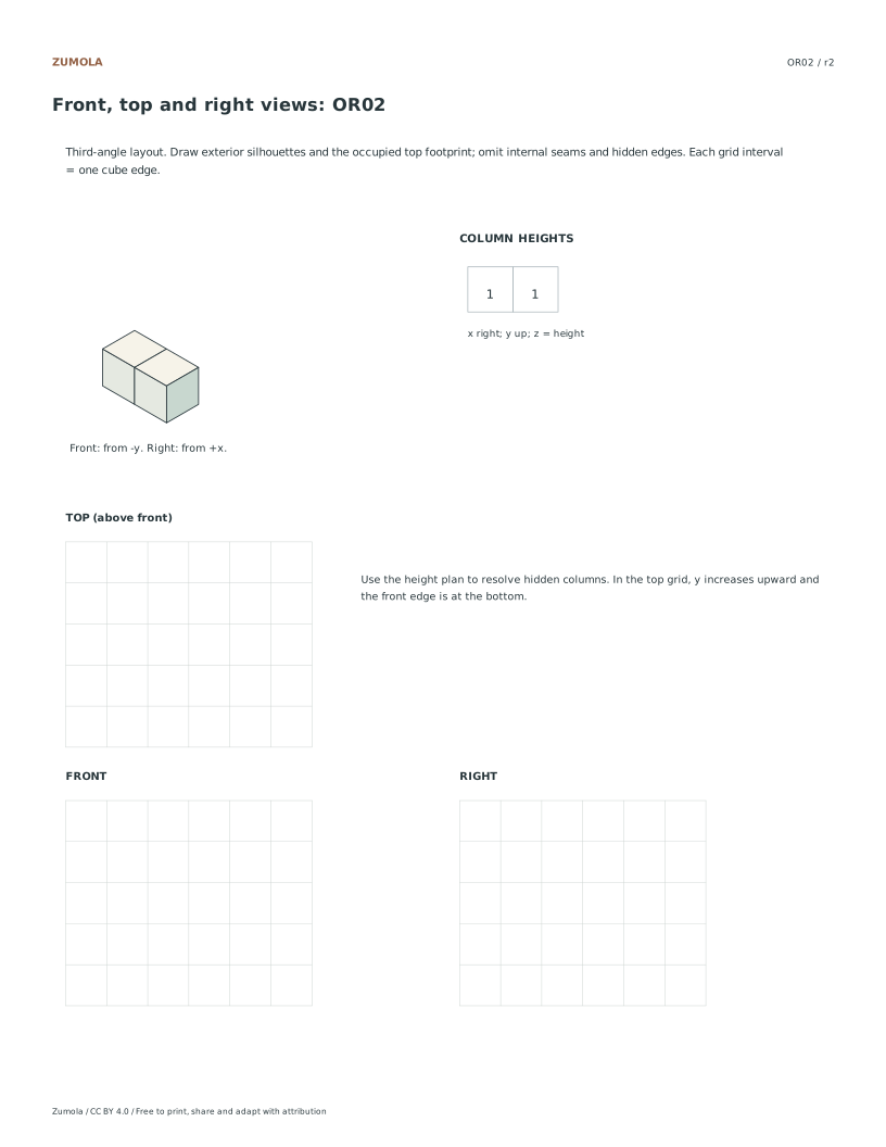
Turn 12 original block models into front, top and right views. An explicit height plan removes hidden-cube guesswork; each solution shows the exterior silhouettes.

12 models.
Third-angle layout.
Silhouettes & footprints only.

Choose your paper and download

Download paper size

Every worksheet and answer is free. No signup.

The complete collection

One pack for each version.

Download the student pack for practice and the separate answer pack to compare. Individual editable sheets appear below. The paper-size choice applies to every download button.

12 pages per file · free · CC BY 4.0

All paper sizes & editable formats
US Letter
A4

Read one height plan in three directions

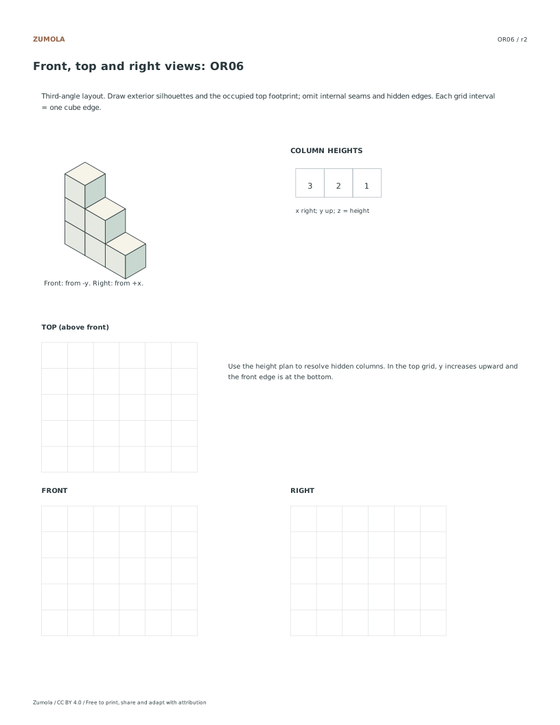
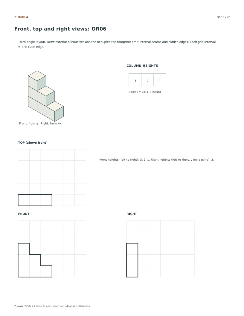
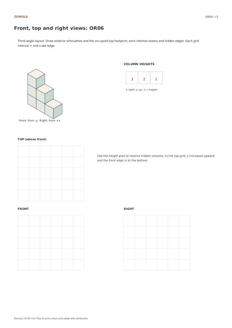
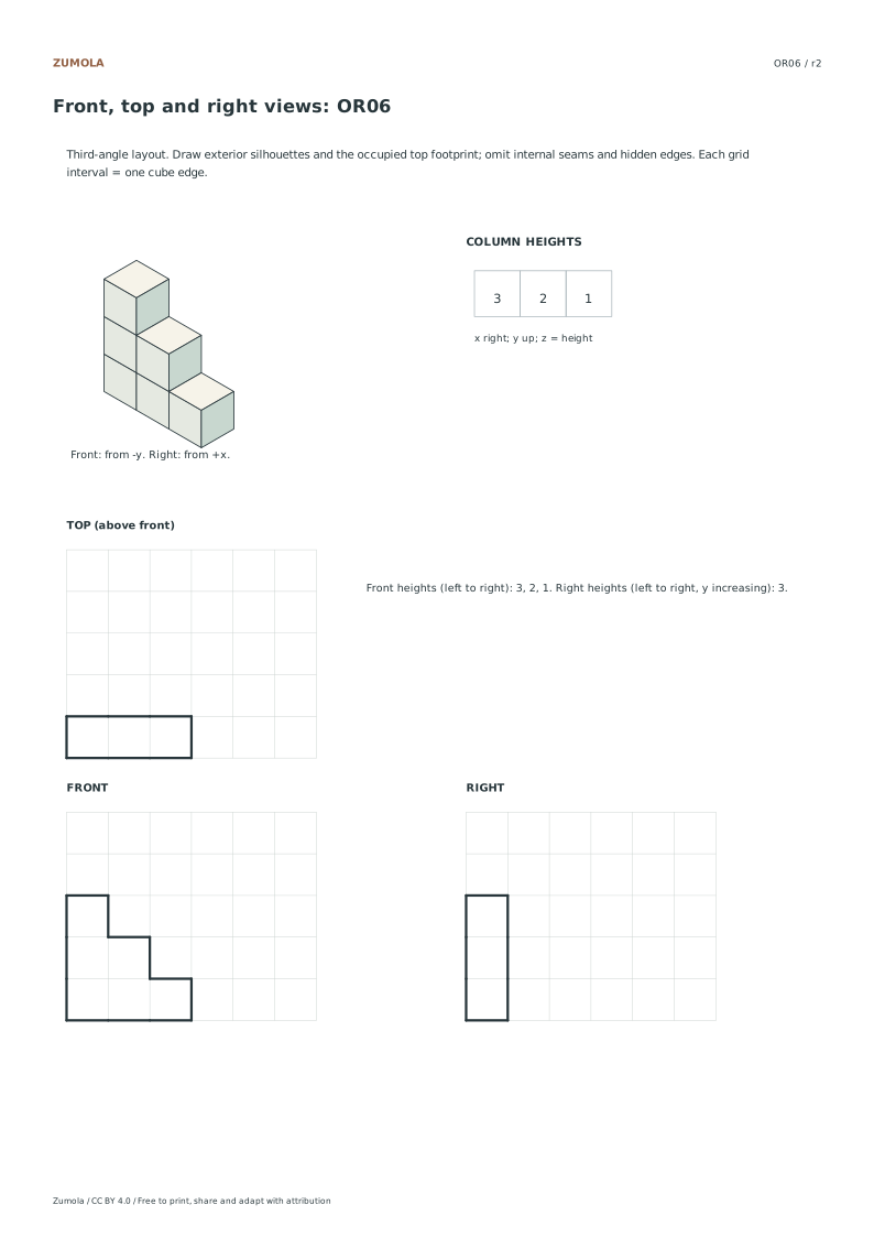
OR06 modelExact result
Column heights, y = 03, 2, 1
Front silhouette heights, x increasing3, 2, 1
Right silhouette heights, y increasing3
Top occupied footprintThree cells in one row

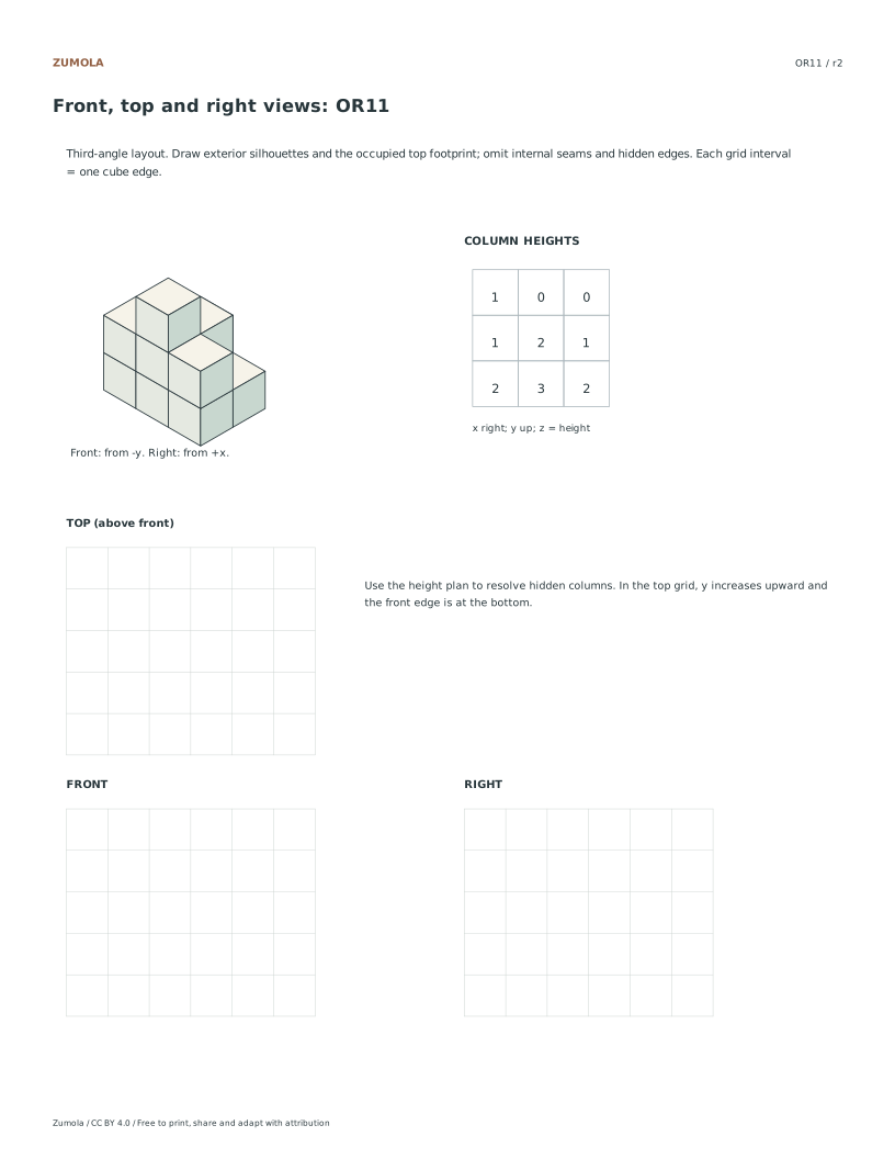
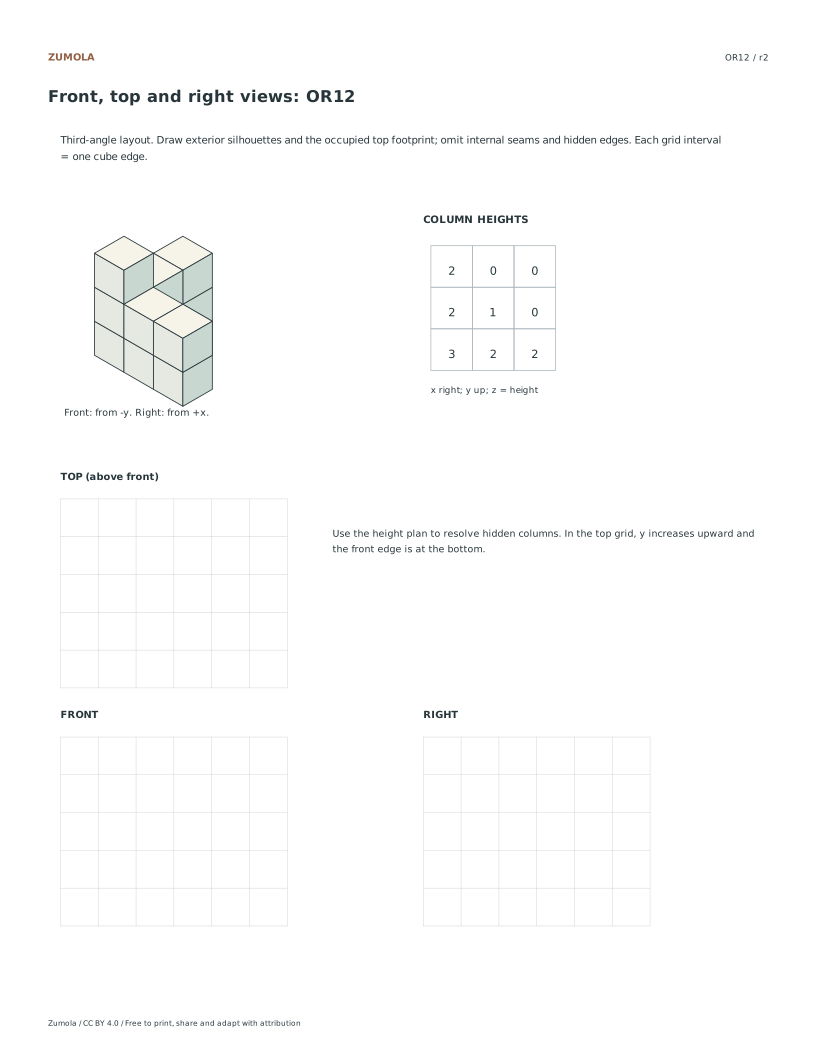
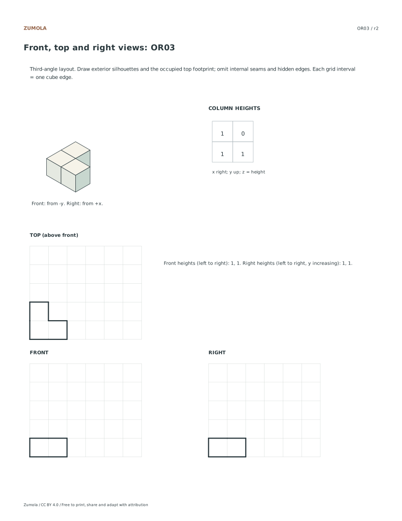
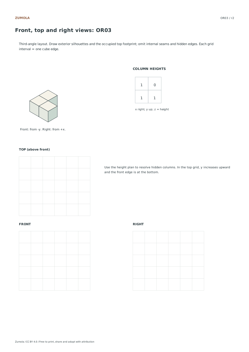
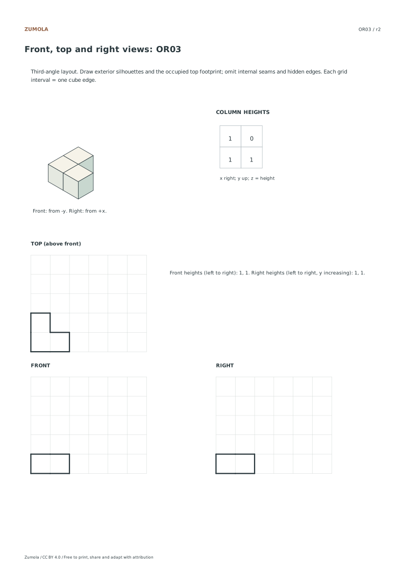
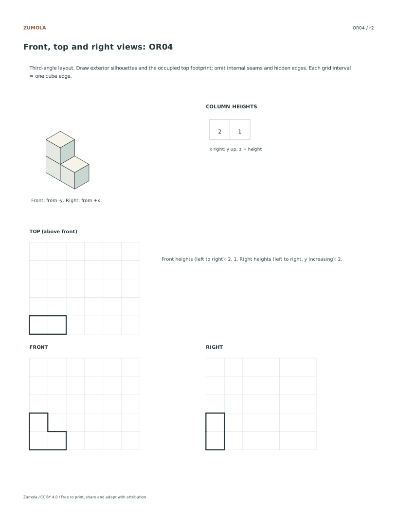
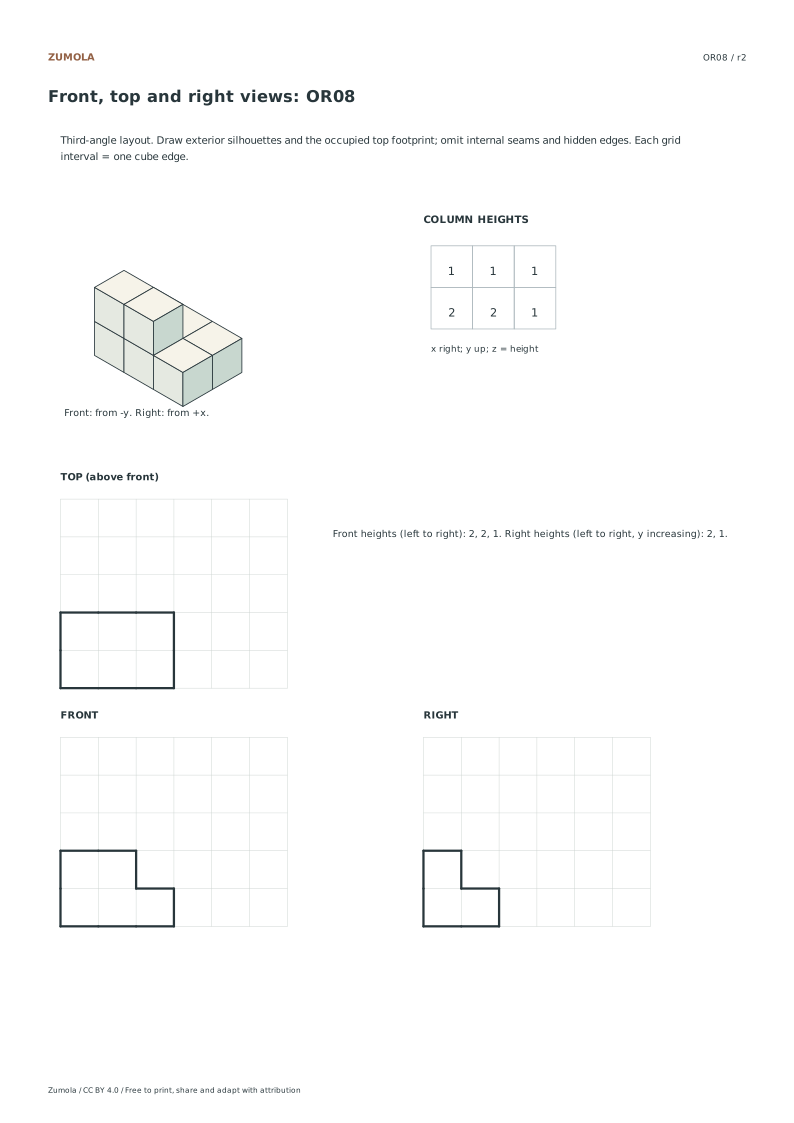
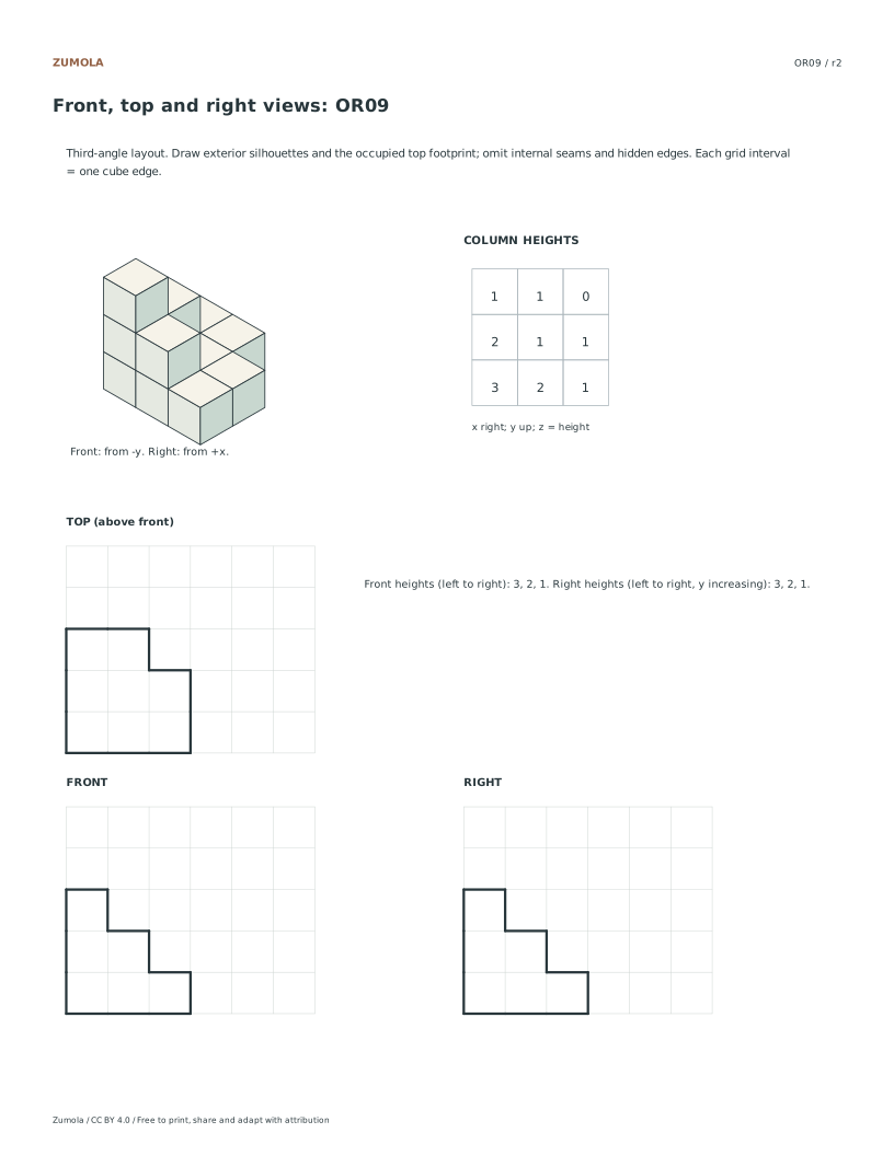
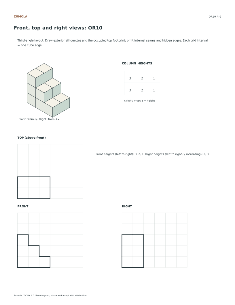
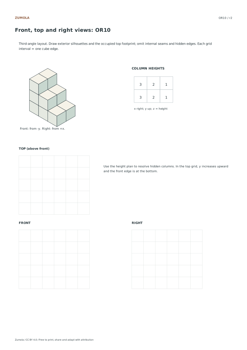
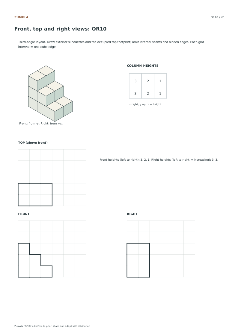
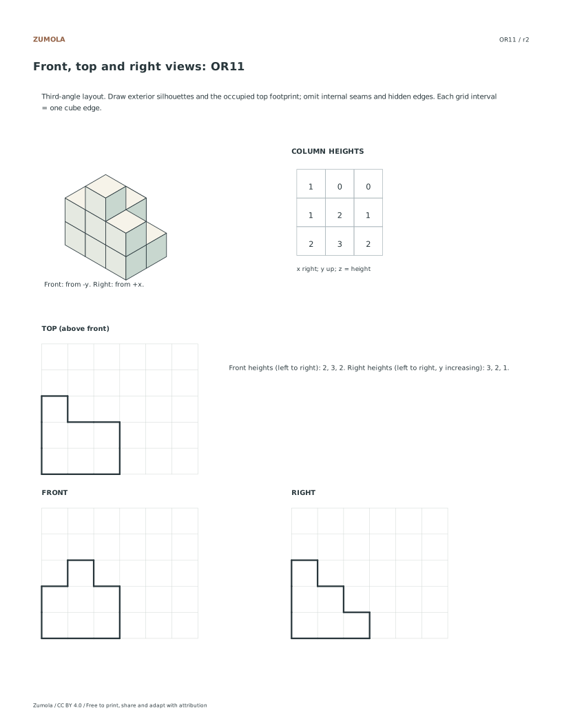
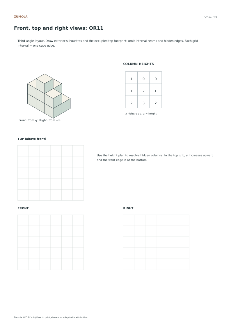
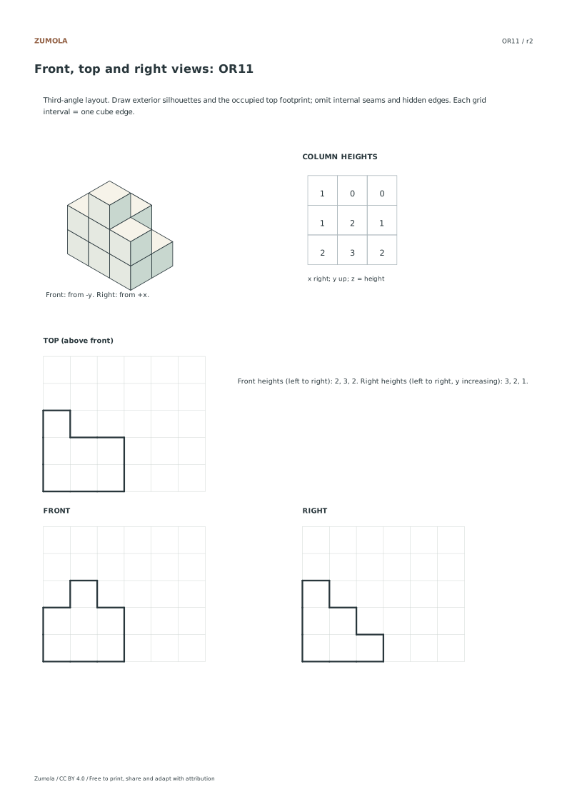
The front observer looks from negative y toward positive y. The right observer looks from positive x toward negative x, so y increases rightward in that view. The top view places the front edge at its bottom and y increases upward. In this third-angle exercise, top sits above front, and right sits to the right of front.

Scope of the answer. These are silhouette and footprint exercises, not complete manufacturing drawings. Internal step edges, cube seams and hidden edges are intentionally omitted. The height plan defines all columns, including those hidden in the isometric picture.
Work through the page

  1. Establishing the Front View

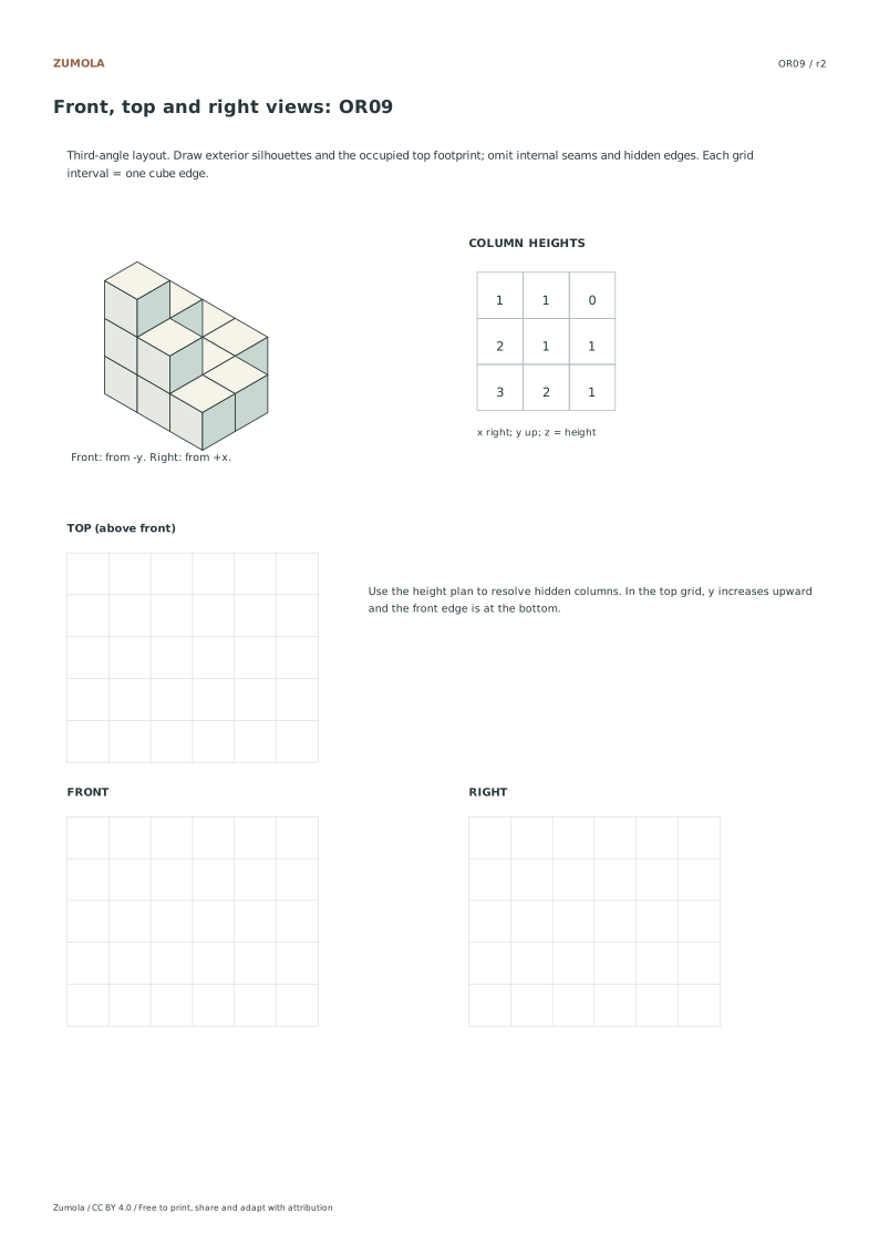
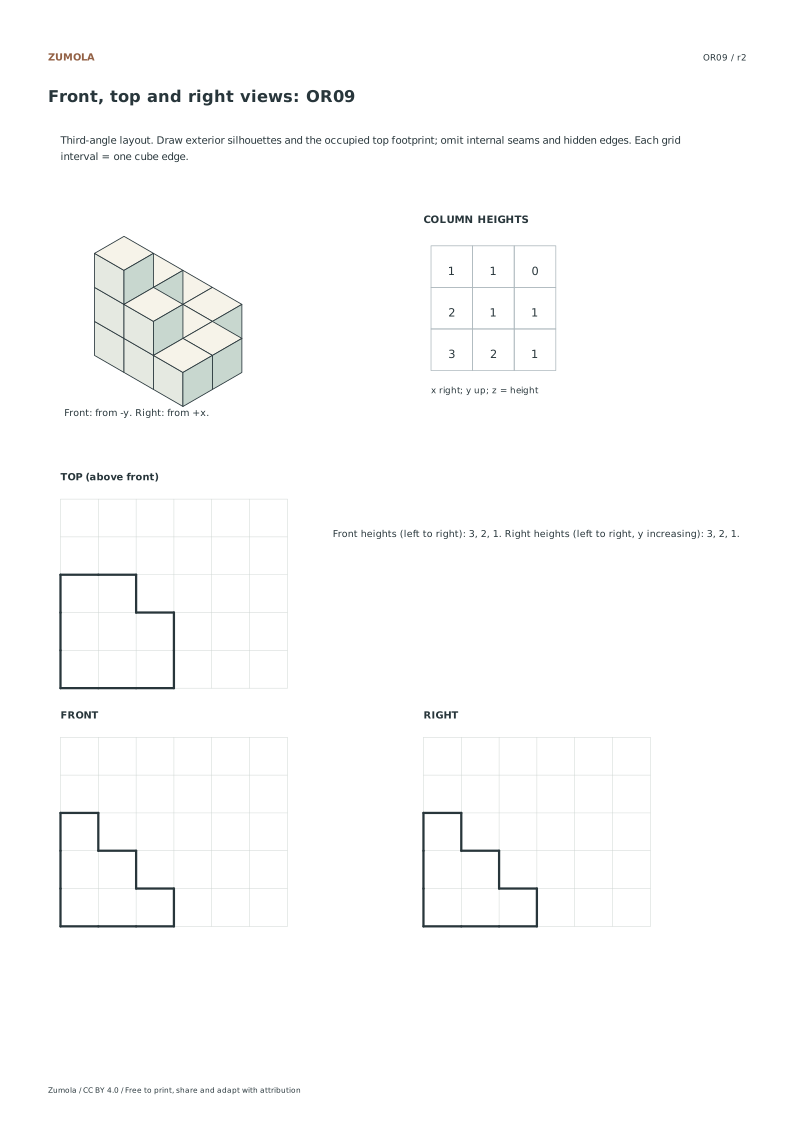
    Begin by orienting the model so the front face is visible from negative y toward positive y. The x-axis increases to the right, defining the horizontal span of your drawing. For each column position along the x-axis, determine the maximum height across all y-values. This maximum value dictates the vertical extent of the silhouette at that specific x-coordinate. Draw only the outer boundary of this profile. Do not include internal seams or hidden edges, as these are deliberately omitted for beginning exercises. The resulting shape represents the front elevation, showing the tallest stack at each horizontal position without revealing depth details behind the frontmost cubes.
  2. Constructing the Right View

    Rotate your perspective to view the model from positive x toward negative x. In this third-angle layout, the right view is placed to the right of the front view. The y-axis increases to the right on this specific view sheet. For each column position along the y-axis, calculate the maximum height across all x-values. This maximum determines the vertical height of the silhouette at that y-coordinate. Draw the outer boundary only, ignoring internal structures. This profile reveals the tallest stack at each depth position, providing a clear side elevation that complements the front view without showing hidden edges or internal seams.

  3. Mapping the Top Footprint

    Position the top view above the front view according to third-angle projection rules. On the sheet, x increases to the right and y increases upward, with the front edge located at the bottom. Identify every grid position where a solid stack exists from z=0. Draw the outline of these occupied positions to create the top footprint. This view shows the horizontal layout of the columns. Do not draw height indicators or hidden lines. The footprint confirms which x and y coordinates contain at least one cube. This simple outline helps verify the base area and aligns with the silhouettes generated in the front and right views for a complete spatial understanding.

Small checks that catch common errors

Watch forCheck instead
Drawing internal seams between adjacent columns in the front or right views.Omit internal seams and hidden edges entirely. Draw only the outer silhouette of the maximum heights for each column position.
Placing the top view below the front view or misaligning the axes.Place the top view above the front view. Ensure x increases to the right and y increases upward on the top view sheet.
Using average heights instead of maximum heights for the front and right profiles.Calculate the maximum height over all y-values for the front view and over all x-values for the right view to define the silhouette.

Before you begin

Useful answers

Why are hidden edges not shown in the drawings?

Internal seams and hidden edges are deliberately omitted for these beginning exercises. The focus is on drawing the outer silhouettes and top footprint only, simplifying the visual interpretation of the solid stacks.

How do I determine the height for each column in the views?

For the front view, take the maximum height across all y-values for each x-position. For the right view, take the maximum height across all x-values for each y-position. This defines the silhouette.

What does the top view represent if heights are not shown?

The top view shows the footprint of the model. It outlines every grid position where a solid stack exists from z=0, indicating which x and y coordinates are occupied without showing vertical height.

Are the answers and editable files free too?

Yes. Every linked PDF, SVG, worksheet and answer is free without signup. The original resources use CC BY 4.0: credit Zumola, link the license and indicate changes. Analytics consent is not required to download or use the resources.

Keep practicing

Further reading: NWTC Technical Sketching: third-angle view layout. The downloadable geometry and exercises on this page are original Zumola work.

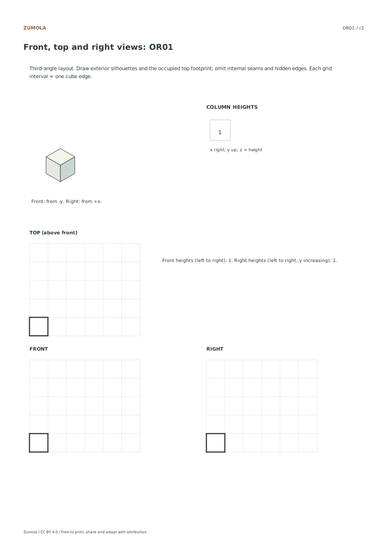
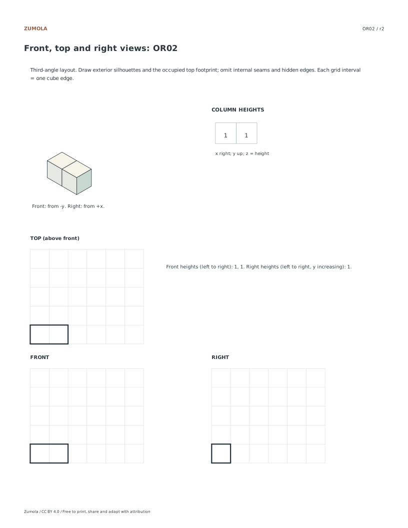
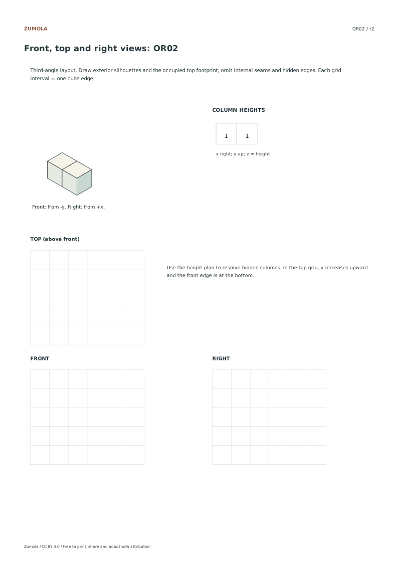
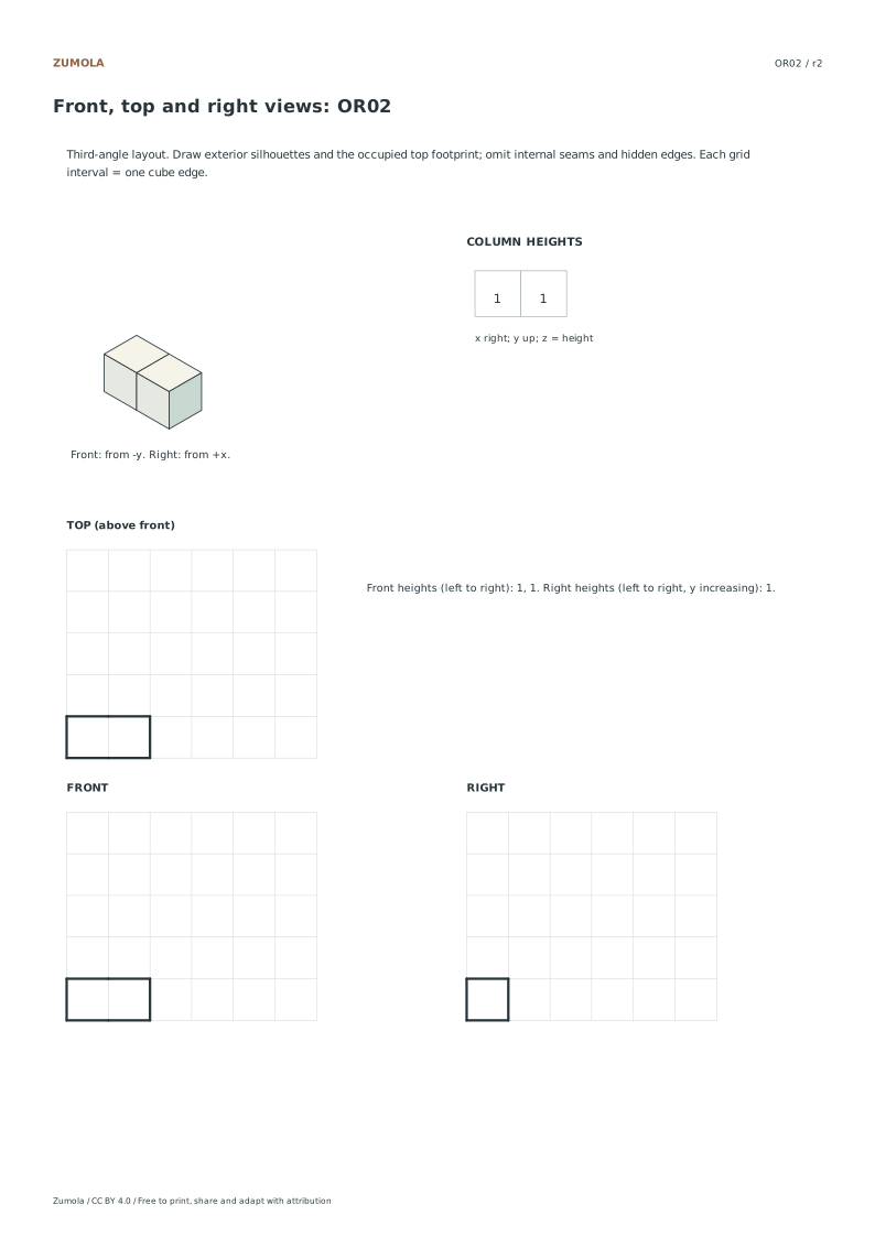
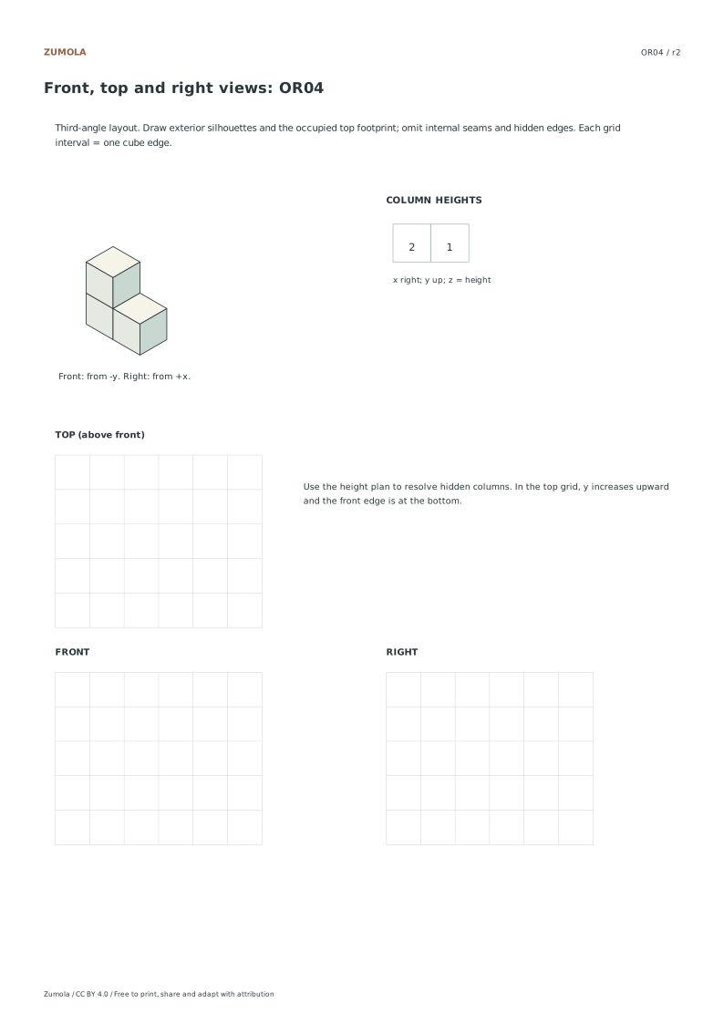
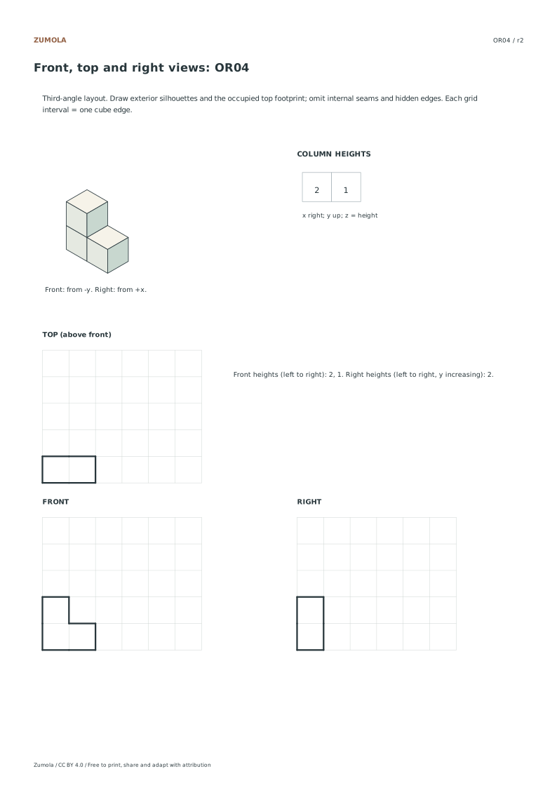
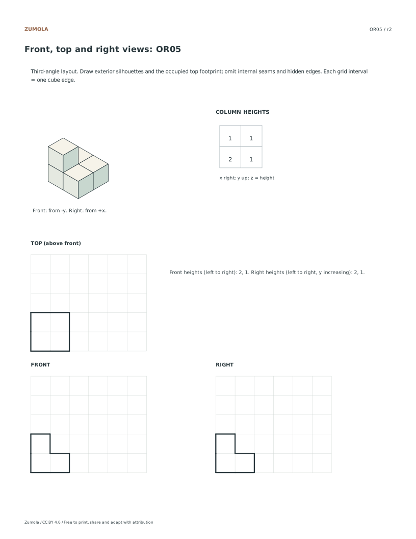
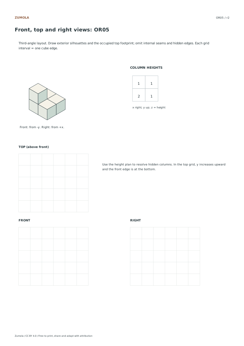
Worksheet preview

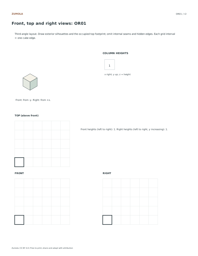
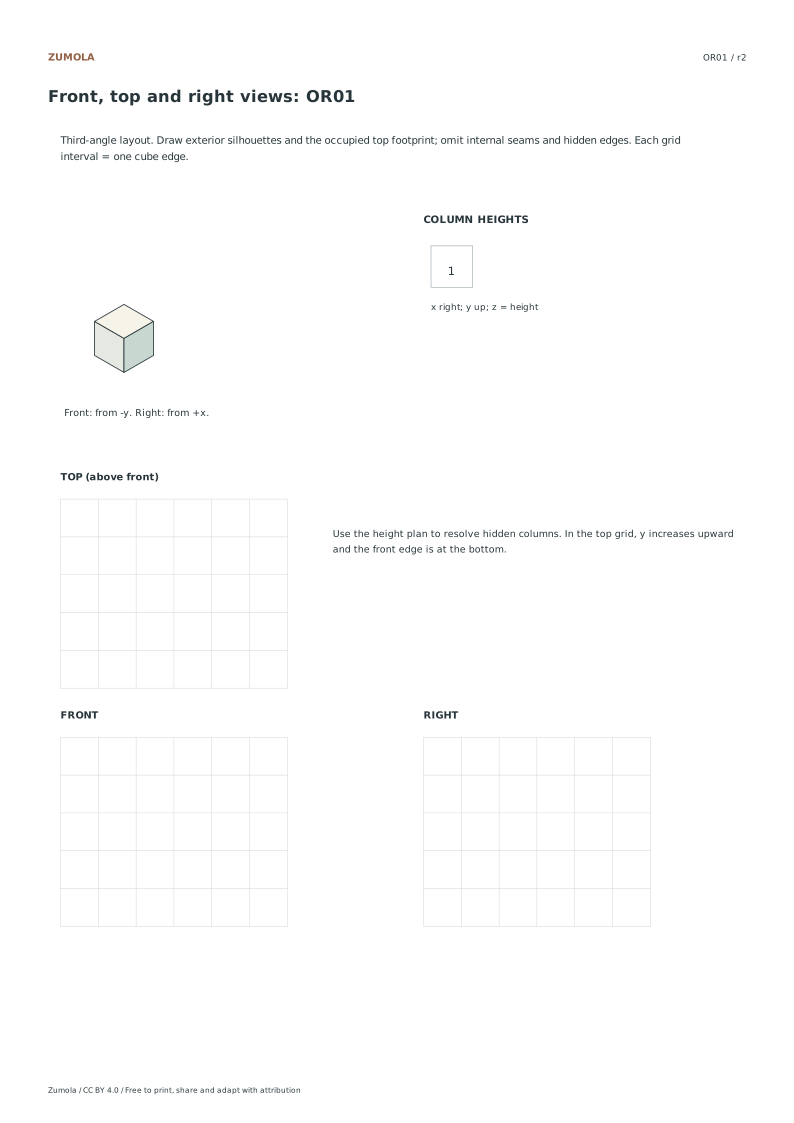
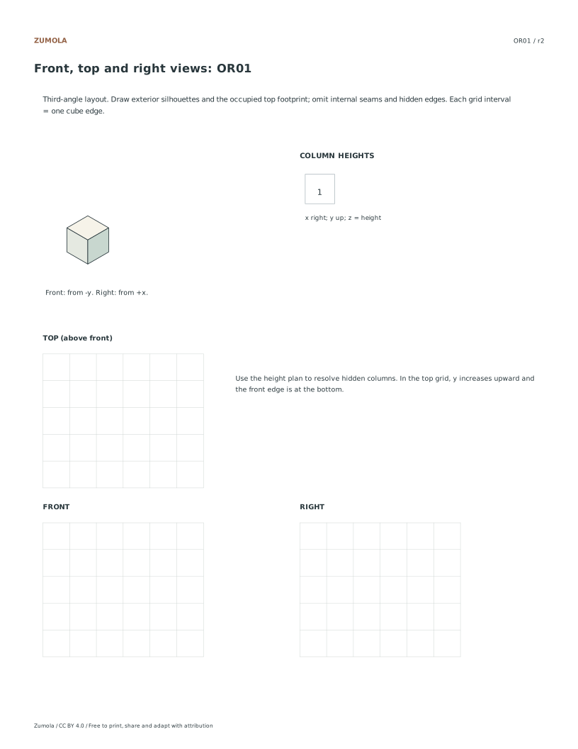
Full printable sheet preview

Fit-to-screen preview. Download the PDF to print at actual size.