Free original lessons
Draw a Plant Stem: Leaf-Node Joints and Taper Construction
Learn to draw a plant stem with clear leaf-node joints and controlled taper using a simple convention, worked example, and four practice tasks.
Free lesson
Four exercises
Worked answers
Object Drawing Lessons
This lesson teaches a reliable method for drawing a plant stem study that focuses on two structural features: leaf-node joints and taper. You will use a simple convention for stem width and node placement, then apply it to four self-contained exercises. The goal is not a single correct drawing but a construction that can be checked with arithmetic and visual comparison. All measurements are hypothetical examples; measure your own paper and tools before drawing.
Practice materials: Printable downloads are not available for this lesson yet. Use the instructions and four exercises below.
Reference illustration
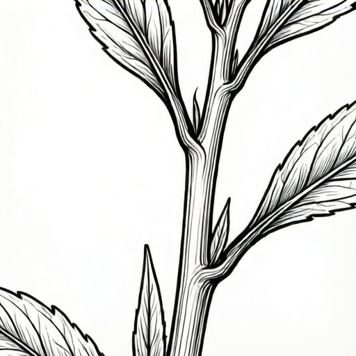
Use the stated measurements and conventions for each exercise.
Convention for Stem Width and Node Placement
Define a stem axis as a straight or gently curved centerline. Mark the baseline at the bottom of the study and the midline at the top of the intended stem length. The x-height is the distance from baseline to midline; use this as your reference unit for node spacing. Letter styles vary, so choose a consistent unit and state it on your page.
For this lesson, use a hypothetical stem width of 6 mm at the base and 3 mm at the top. Node spacing is measured along the axis from baseline to midline. Place nodes at 25 percent, 55 percent, and 80 percent of the axis length. These values are examples only; adjust them to your paper size and keep the arithmetic simple.
- Draw a vertical axis and mark baseline and midline.
- Measure the axis length and calculate node positions at 25, 55, and 80 percent.
- Mark stem width at base (6 mm) and top (3 mm), then interpolate width at each node.
- Draw two smooth side lines connecting the width marks, keeping taper gradual.
- At each node, draw a short joint line perpendicular to the axis to represent the leaf-node attachment.
Constructing Taper Without Bulges
Taper means the stem narrows gradually from base to top. Avoid sudden width changes at nodes. A useful check is to compare the width at each node to a linear interpolation between base and top widths. For a 6 mm base and 3 mm top over three equal segments, the widths at 25, 55, and 80 percent are approximately 5.25 mm, 4.35 mm, and 3.6 mm.
Draw the side lines as smooth curves that pass through these width marks. If a node joint makes the stem look wider, reduce the joint line length rather than changing the stem width. The joint should suggest attachment, not a bulge.
- Calculate interpolated widths at each node using simple arithmetic.
- Mark width points on both sides of the axis at each node.
- Connect width points with smooth side lines, checking that no segment reverses taper.
- Draw joint lines at nodes, keeping them shorter than the local stem width.
- Compare the finished stem to the width marks and adjust side lines if needed.
Leaf-Node Joint Examples and Spacing
A leaf-node joint is where a leaf attaches to the stem. In this study, represent it as a short line crossing the stem at the node, angled slightly upward. Vary the angle between 30 and 60 degrees from the axis to show natural variation. The joint line should not extend beyond the stem width by more than half the local width.
Node spacing affects the rhythm of the drawing. Using the 25, 55, and 80 percent positions creates uneven spacing that looks natural. Check spacing by measuring from baseline to each node and comparing to your calculated values. If a node is off by more than 2 mm, reposition it before adding joint lines.
- Mark node positions along the axis using calculated percentages.
- Draw a short joint line at each node, angled upward.
- Check joint line length against local stem width.
- Measure node spacing and correct any node more than 2 mm from its target.
- Review the overall rhythm and adjust joint angles for variety.
Checking Your Stem Study
Use a simple checklist: axis is straight or smoothly curved; baseline and midline are marked; node positions match calculated percentages within 2 mm; stem width at base and top matches chosen values; taper is gradual with no bulges; joint lines are shorter than local stem width and angled upward.
Because letter styles and drawing conventions vary, accept any consistent convention that is stated on the page. The rubric below allows valid alternatives as long as the construction is checkable and the arithmetic is consistent.
- Measure axis length and node positions.
- Compare stem widths at base, nodes, and top to interpolated values.
- Check joint line lengths and angles.
- Confirm that all measurements use the same unit.
- Record any deviations and decide whether they are acceptable alternatives.
Worked example
Draw a stem study with axis length 120 mm, base width 6 mm, top width 3 mm, and nodes at 25, 55, and 80 percent. Calculate node positions and interpolated widths, then describe the drawing steps.
Worked answer
Node positions: 30 mm, 66 mm, and 96 mm from baseline. Interpolated widths: at 25 percent, 6 minus 0.25 times 3 equals 5.25 mm; at 55 percent, 6 minus 0.55 times 3 equals 4.35 mm; at 80 percent, 6 minus 0.80 times 3 equals 3.6 mm. Draw axis, mark baseline and midline, mark node positions, mark width points at each node, connect with smooth side lines, and add short upward joint lines at each node. Check that no joint line exceeds half the local width beyond the stem.
Four practice exercises
Exercise 1
Axis length 100 mm, base width 8 mm, top width 4 mm, nodes at 20, 50, and 75 percent. Calculate node positions and interpolated widths, then describe the drawing.
Show answer and check
Node positions: 20 mm, 50 mm, and 75 mm. Widths: at 20 percent, 8 minus 0.20 times 4 equals 7.2 mm; at 50 percent, 8 minus 0.50 times 4 equals 6.0 mm; at 75 percent, 8 minus 0.75 times 4 equals 5.0 mm. Draw axis, mark positions, mark widths, connect side lines smoothly, add short upward joint lines.
Why: Interpolation uses base width minus fraction times difference between base and top widths. Node positions are percentages of axis length.
Check: Measure node positions from baseline and compare to 20, 50, and 75 mm within 2 mm. Measure widths at nodes and compare to 7.2, 6.0, and 5.0 mm within 1 mm.
Exercise 2
Axis length 80 mm, base width 5 mm, top width 2 mm, nodes at 30, 60, and 90 percent. Calculate and describe the drawing.
Show answer and check
Node positions: 24 mm, 48 mm, and 72 mm. Widths: at 30 percent, 5 minus 0.30 times 3 equals 4.1 mm; at 60 percent, 5 minus 0.60 times 3 equals 3.2 mm; at 90 percent, 5 minus 0.90 times 3 equals 2.3 mm. Draw axis, mark positions, mark widths, connect side lines, add joint lines.
Why: The difference between base and top widths is 3 mm. Multiply by each fraction and subtract from base width.
Check: Verify node positions within 2 mm of 24, 48, and 72 mm. Verify widths within 1 mm of 4.1, 3.2, and 2.3 mm.
Exercise 3
Axis length 150 mm, base width 9 mm, top width 3 mm, nodes at 10, 40, and 70 percent. Calculate and describe the drawing.
Show answer and check
Node positions: 15 mm, 60 mm, and 105 mm. Widths: at 10 percent, 9 minus 0.10 times 6 equals 8.4 mm; at 40 percent, 9 minus 0.40 times 6 equals 6.6 mm; at 70 percent, 9 minus 0.70 times 6 equals 4.8 mm. Draw axis, mark positions, mark widths, connect side lines, add joint lines.
Why: Difference between base and top widths is 6 mm. Interpolate at each node fraction.
Check: Measure node positions within 2 mm of 15, 60, and 105 mm. Measure widths within 1 mm of 8.4, 6.6, and 4.8 mm.
Exercise 4
Axis length 60 mm, base width 4 mm, top width 1 mm, nodes at 35, 65, and 85 percent. Calculate and describe the drawing.
Show answer and check
Node positions: 21 mm, 39 mm, and 51 mm. Widths: at 35 percent, 4 minus 0.35 times 3 equals 2.95 mm; at 65 percent, 4 minus 0.65 times 3 equals 2.05 mm; at 85 percent, 4 minus 0.85 times 3 equals 1.45 mm. Draw axis, mark positions, mark widths, connect side lines, add joint lines.
Why: Difference between base and top widths is 3 mm. Multiply by each fraction and subtract from base width.
Check: Verify node positions within 2 mm of 21, 39, and 51 mm. Verify widths within 1 mm of 2.95, 2.05, and 1.45 mm.
Common mistakes
- Making the stem wider at a node than between nodes. Keep joint lines shorter than the local stem width and redraw side lines smoothly through width marks.
- Using uneven units for axis length and node spacing. State one unit on the page and convert all measurements to that unit before drawing.
- Placing nodes at equal intervals without checking percentages. Calculate 25, 55, and 80 percent of the axis length and mark those positions before drawing joints.
- Drawing taper as a sudden step near the top. Interpolate width at each node and connect marks with smooth side lines.
Self-check rubric
- Axis is straight or smoothly curved and has marked baseline and midline.
- Node positions match calculated percentages within 2 mm.
- Stem width at base and top matches chosen values within 1 mm.
- Taper is gradual with no bulges at nodes.
- Joint lines are shorter than local stem width and angled upward between 30 and 60 degrees.
- All measurements use one stated unit.
- Any alternative convention is stated on the page and applied consistently.
Questions and answers
Do I have to use 6 mm and 3 mm stem widths?
No. Those are hypothetical examples. Choose widths that fit your paper and keep the arithmetic simple.
What if my node spacing looks different from the example?
As long as you state your convention and your measured positions match your calculated percentages within 2 mm, the drawing is valid.
Can joint lines be angled downward?
The convention here uses upward angles between 30 and 60 degrees. If you choose a different consistent convention, state it on the page and apply it throughout.
How do I check taper without a ruler?
Use the width marks you drew at each node. Compare the distance between side lines at each node to your interpolated values.