Reference diagram
LETTER · Download PDF (2 pages)
Free original resources
Learn to draw a bowling lane in one-point perspective, placing the pin triangle and lane arrows correctly using a simple convergence guide.
Original reference diagrams, four practice exercises and separate worked answers. All files are free. No signup required.
LETTER · Download PDF (2 pages)
LETTER · Download PDF (5 pages)
LETTER · Download PDF (6 pages)
Choose A4 or US Letter for your printer. The reference and answer illustrations are not physical rulers; follow the scale instruction printed on the practice worksheet.
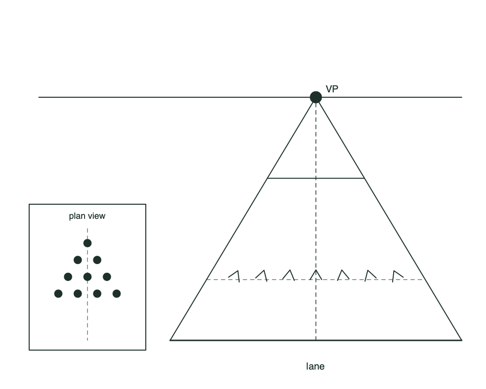
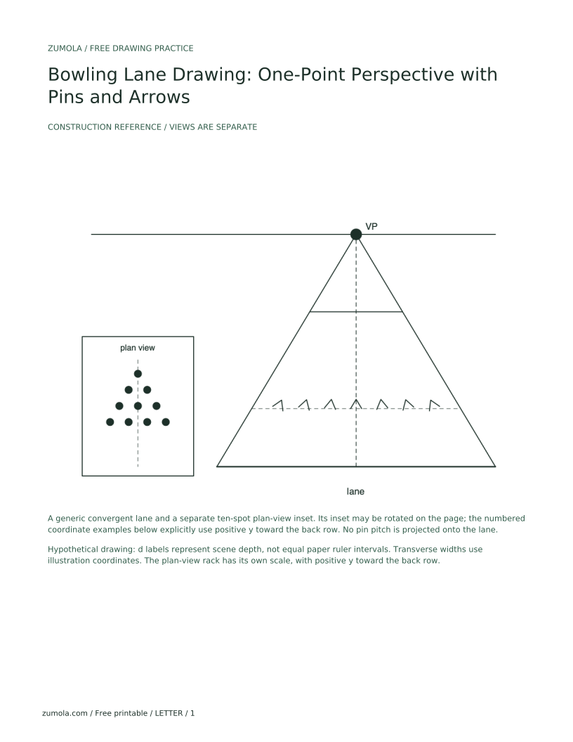
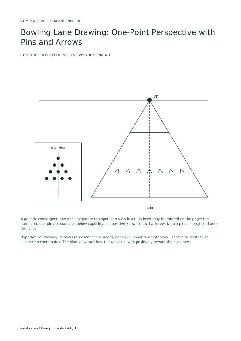
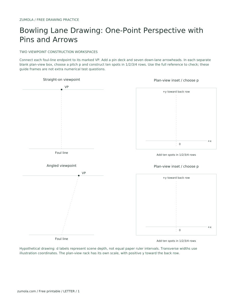
This lesson teaches a reliable method for drawing a bowling lane in one-point perspective. You will set a vanishing point, draw converging gutter lines, and place lane arrow markers at measured intervals. Show the ten pin spots in a separate, clearly labeled plan-view inset beside the lane drawing; the inset preserves their equal triangular spacing and is not a perspective rendering. The focus is on spatial arrangement and perspective, not scoring or bowling action. All illustrative drawing measurements are hypothetical; sourced USBC arrow-distance and pin-spot specifications are identified separately. Valid alternatives are allowed where the convention is stated, provided the lane perspective and the inset geometry are checked separately. Lane lengths and arrow distances denote represented depth, not equally spaced lengths on the printed page. Stated transverse widths are measurements in the illustration coordinate system; the perspective guide foreshortens depth separately.
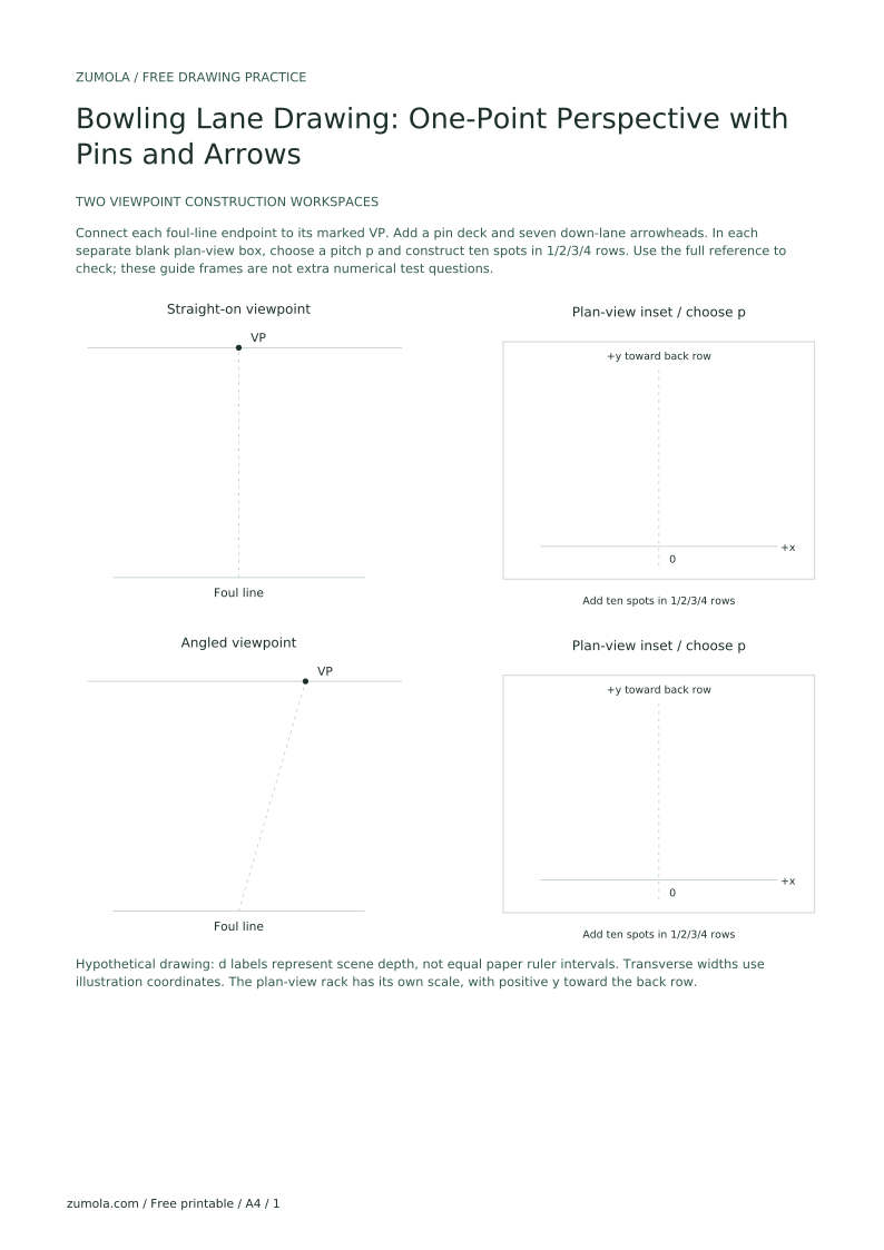
Begin with a horizontal line representing eye level. Choose a vanishing point on this line, centered for a straight-on view or offset for an angled view. The foul line is a horizontal segment near the bottom of the page. From the ends of the foul line, draw two lines that converge at the vanishing point; these are the gutter edges. The lane surface lies between them.
Keep represented depth separate from distance measured on the paper. A lane labeled 10 depth units represents a chosen distance down the scene; it is not ten equal ruler intervals along the printed centerline. Foreshorten those depth positions using the supplied perspective guide, with the pin-deck segment meeting both converging gutter edges. The foul-line and cross-section widths are given measurements in the illustration. A pin-deck width about one-third of the foul-line width is an optional hypothetical visual choice, not a regulation or an extra requirement imposed on every numerical example. All widths must agree with the chosen vanishing point and foreshortened depth guide.
The ten-pin rack is triangular: one head pin nearest the bowler, then rows of two, three, and four farther away. USBC equipment specifications state that the ten pin spots are spaced 12 inches apart in an equilateral triangle. This lesson shows that rack as a separate plan-view inset, not as pins projected onto the perspective lane. Let p be the center-to-center pitch in the inset: for a true-size layout p=12 inches; for a drawing, choose any convenient scale.
For a self-contained construction, use the head pin at (0,0), with positive y pointing toward the back row. Put row two at (−p/2, √3p/2) and (p/2, √3p/2); row three at (−p, √3p), (0, √3p), and (p, √3p); and row four at (−3p/2, 3√3p/2), (−p/2, 3√3p/2), (p/2, 3√3p/2), and (3p/2, 3√3p/2). These plan-view centers make every adjacent pitch p. Do not describe their equal spacing as shrinking with distance. Projecting this pattern onto the perspective lane is outside this worksheet convention.
The USBC High School Bowling Coaching Guide describes seven lane arrows, approximately 12–16 feet from the foul line, as targets. The worksheet below simplifies their placement to seven evenly spaced markers at one shared transverse cross-section, one on the center line and three on each side. This shared row and its equal spacing are drawing conventions, not assertions about a required equipment layout. Do not arrange this worksheet row in a V. Each individual marker may be a small triangle or chevron pointed down-lane toward the vanishing point.
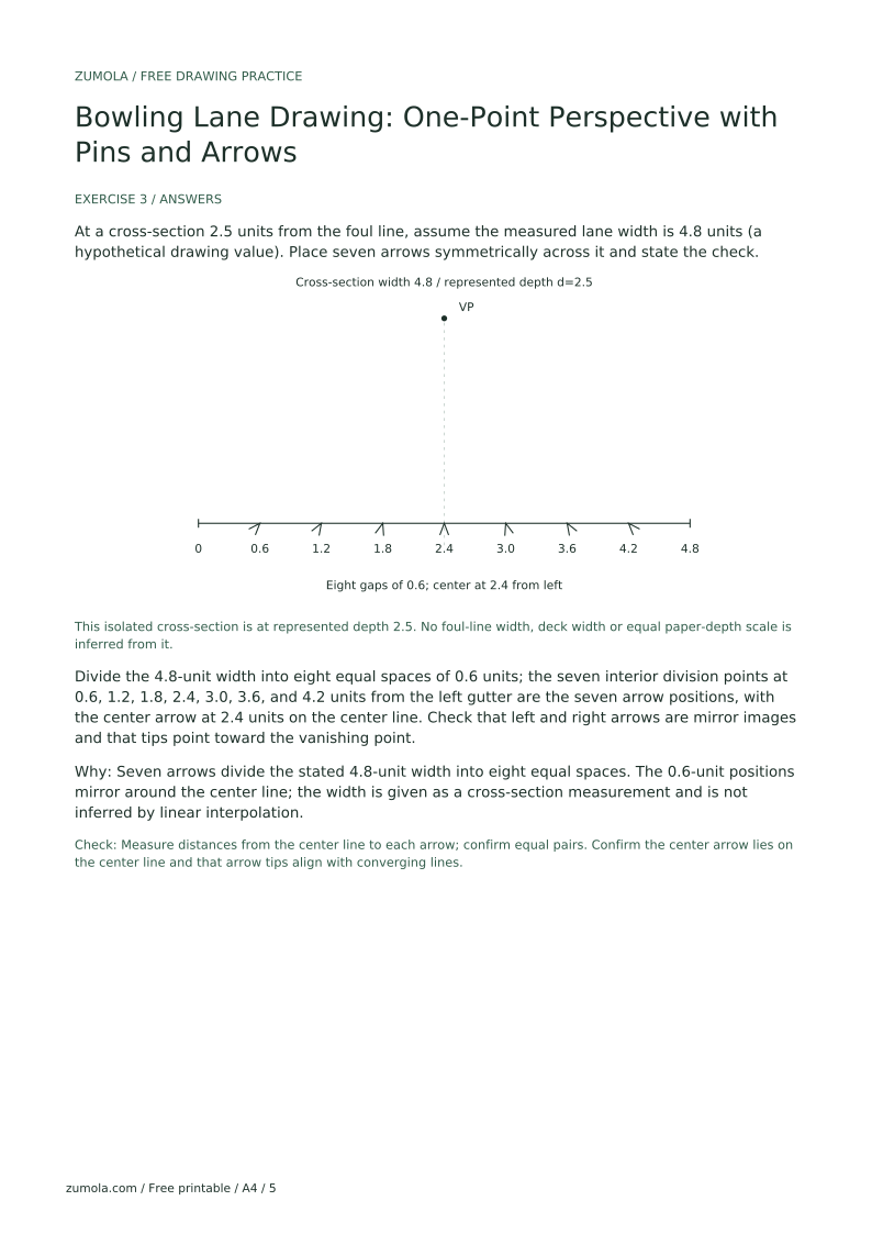
For a represented-depth example, let 10 depth units stand for 60 feet. The USBC target distance of about 12–16 feet corresponds to about 2–2.7 depth units; choose 2.5 to represent 15 feet. Locate that represented depth with the foreshortened guide, not by measuring 2.5 equal paper units along the lane. At that cross-section, use the stated width between gutter lines. Divide it into eight equal spaces and place seven markers at the interior division points. These transverse positions belong to the illustration coordinate system; do not use them to infer a linear depth scale. Arrowheads point toward the vanishing point while their tip row stays transverse.
Check the lane perspective and the pin inset separately. First, the gutter edges and lane centerline should converge consistently toward the vanishing point, while the arrow row stays transverse and symmetric on the measured lane cross-section. Second, the ten pin spots in the labeled plan-view inset should form one centered triangular lattice with the stated pitch p. The inset is top-down, so its equal gaps remain equal; do not compare them to perspective gaps on the lane.
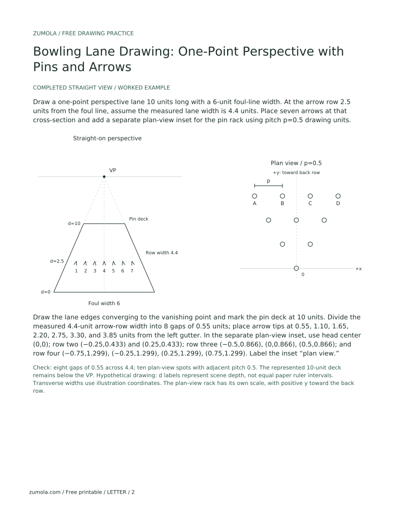
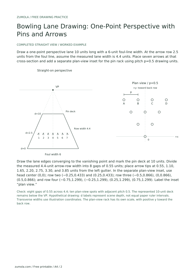
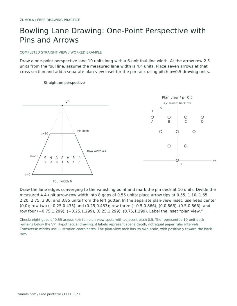
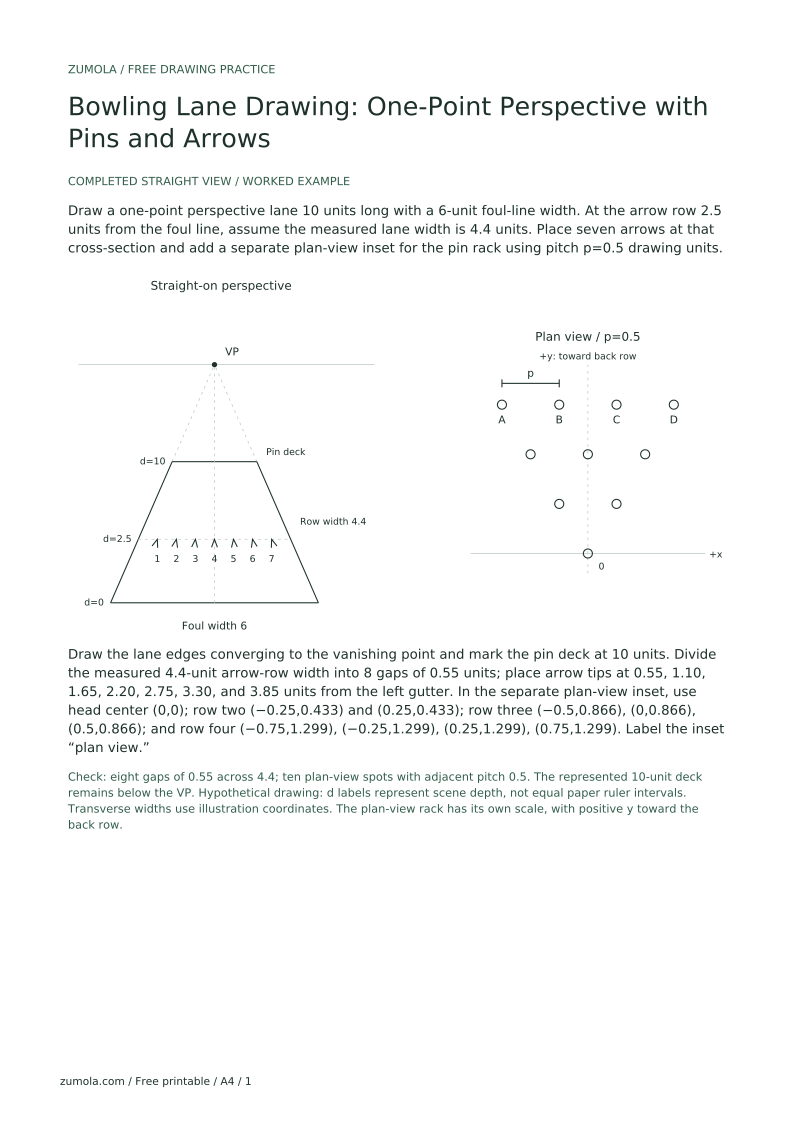
For the worked lane example, the lane is 10 units long and the arrow row is placed 2.5 units from the foul line. At the stated 4.4-unit width, seven arrows make eight equal gaps of 0.55 units, with the center at 2.2 units. For a separate pin inset with p=0.5 drawing units, the back row centers are at x=−0.75, −0.25, 0.25, 0.75 and y=3√3/4≈1.299. Their three adjacent horizontal gaps are each 0.5 units. These are two different views and coordinate systems: the arrow row belongs to the perspective lane, while the rack coordinates belong to the plan-view inset.
Draw a one-point perspective lane 10 units long with a 6-unit foul-line width. At the arrow row 2.5 units from the foul line, assume the measured lane width is 4.4 units. Place seven arrows at that cross-section and add a separate plan-view inset for the pin rack using pitch p=0.5 drawing units.
Draw the lane edges converging to the vanishing point and mark the pin deck at 10 units. Divide the measured 4.4-unit arrow-row width into 8 gaps of 0.55 units; place arrow tips at 0.55, 1.10, 1.65, 2.20, 2.75, 3.30, and 3.85 units from the left gutter. In the separate plan-view inset, use head center (0,0); row two (−0.25,0.433) and (0.25,0.433); row three (−0.5,0.866), (0,0.866), (0.5,0.866); and row four (−0.75,1.299), (−0.25,1.299), (0.25,1.299), (0.75,1.299). Label the inset “plan view.”
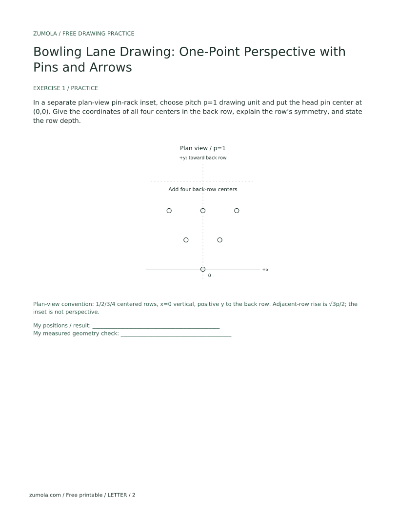
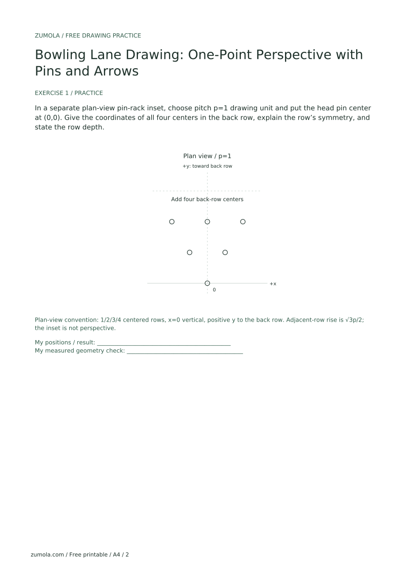
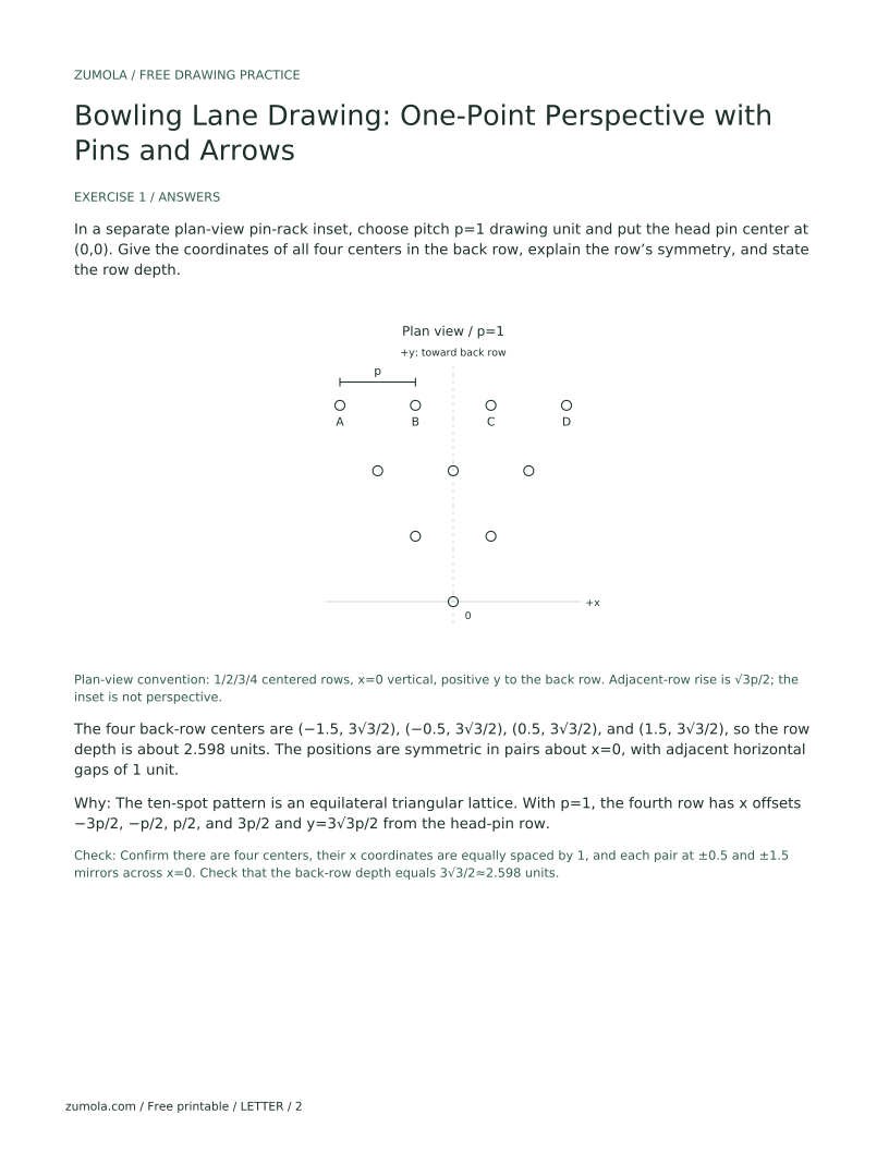
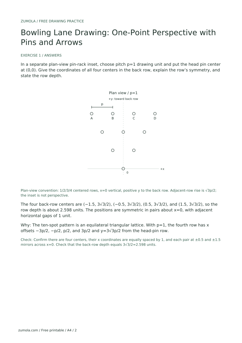
In a separate plan-view pin-rack inset, choose pitch p=1 drawing unit and put the head pin center at (0,0). Give the coordinates of all four centers in the back row, explain the row’s symmetry, and state the row depth.
The four back-row centers are (−1.5, 3√3/2), (−0.5, 3√3/2), (0.5, 3√3/2), and (1.5, 3√3/2), so the row depth is about 2.598 units. The positions are symmetric in pairs about x=0, with adjacent horizontal gaps of 1 unit.
The ten-spot pattern is an equilateral triangular lattice. With p=1, the fourth row has x offsets −3p/2, −p/2, p/2, and 3p/2 and y=3√3p/2 from the head-pin row.
Check: Confirm there are four centers, their x coordinates are equally spaced by 1, and each pair at ±0.5 and ±1.5 mirrors across x=0. Check that the back-row depth equals 3√3/2≈2.598 units.
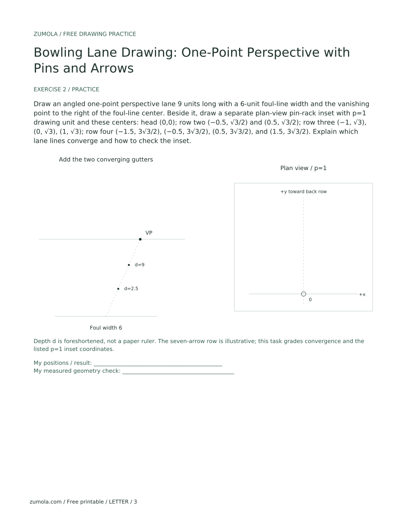
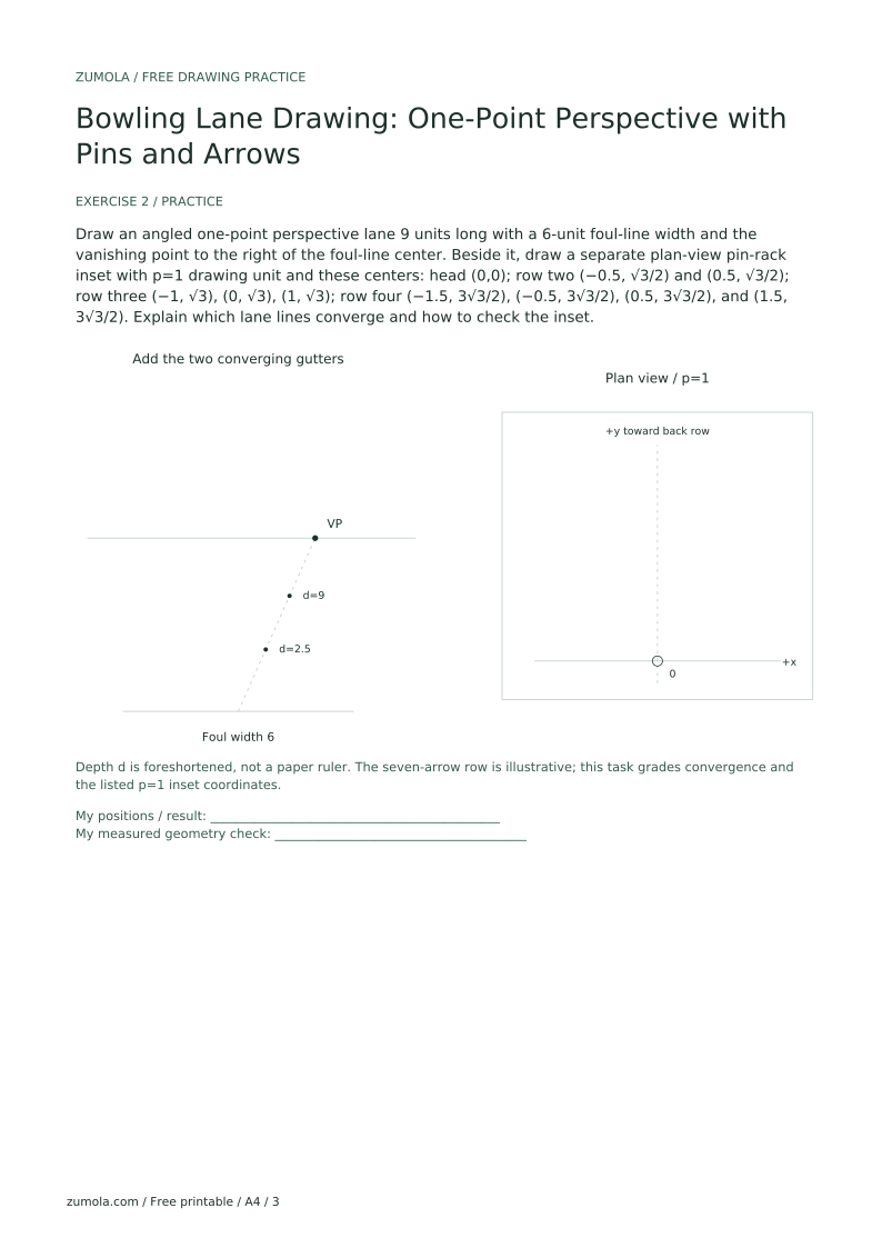
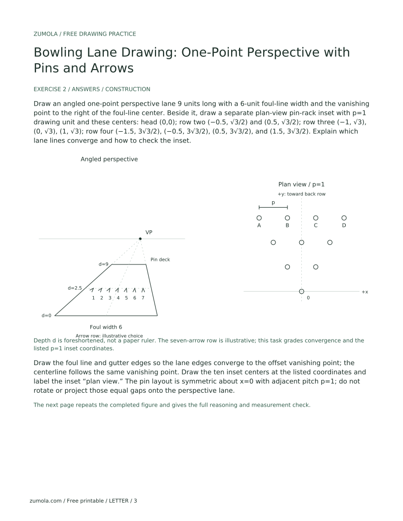
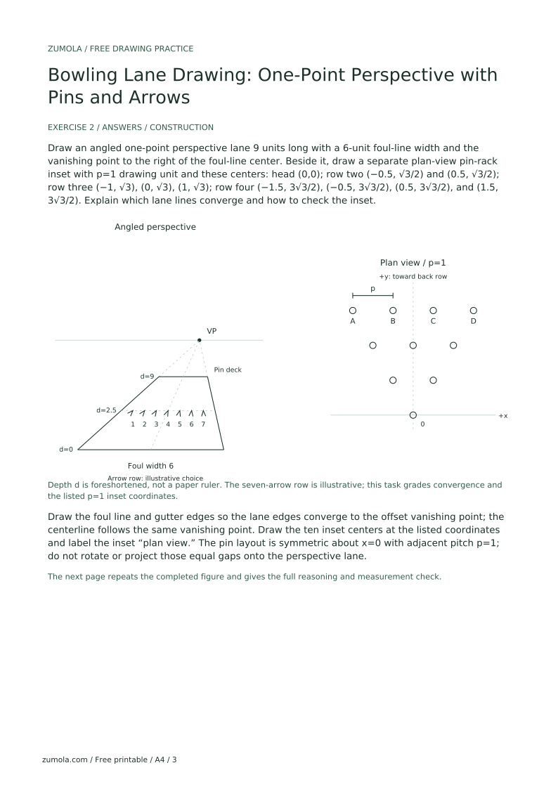
Draw an angled one-point perspective lane 9 units long with a 6-unit foul-line width and the vanishing point to the right of the foul-line center. Beside it, draw a separate plan-view pin-rack inset with p=1 drawing unit and these centers: head (0,0); row two (−0.5, √3/2) and (0.5, √3/2); row three (−1, √3), (0, √3), (1, √3); row four (−1.5, 3√3/2), (−0.5, 3√3/2), (0.5, 3√3/2), and (1.5, 3√3/2). Explain which lane lines converge and how to check the inset.
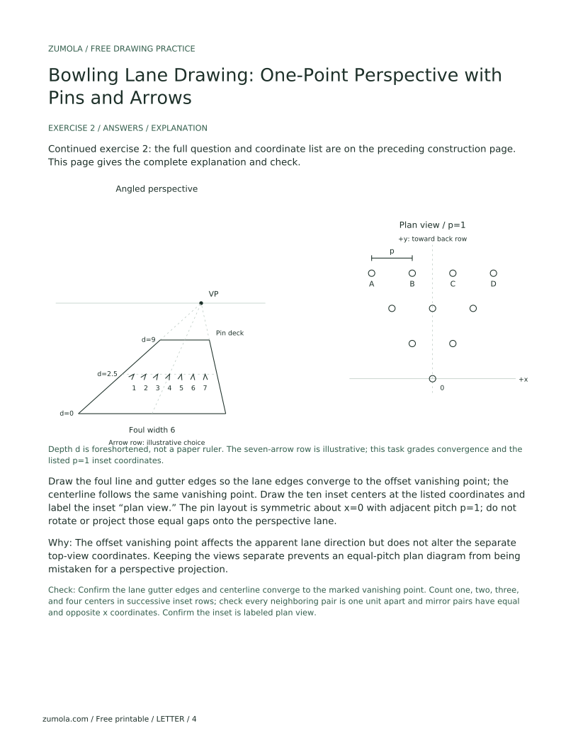
Draw the foul line and gutter edges so the lane edges converge to the offset vanishing point; the centerline follows the same vanishing point. Draw the ten inset centers at the listed coordinates and label the inset “plan view.” The pin layout is symmetric about x=0 with adjacent pitch p=1; do not rotate or project those equal gaps onto the perspective lane.
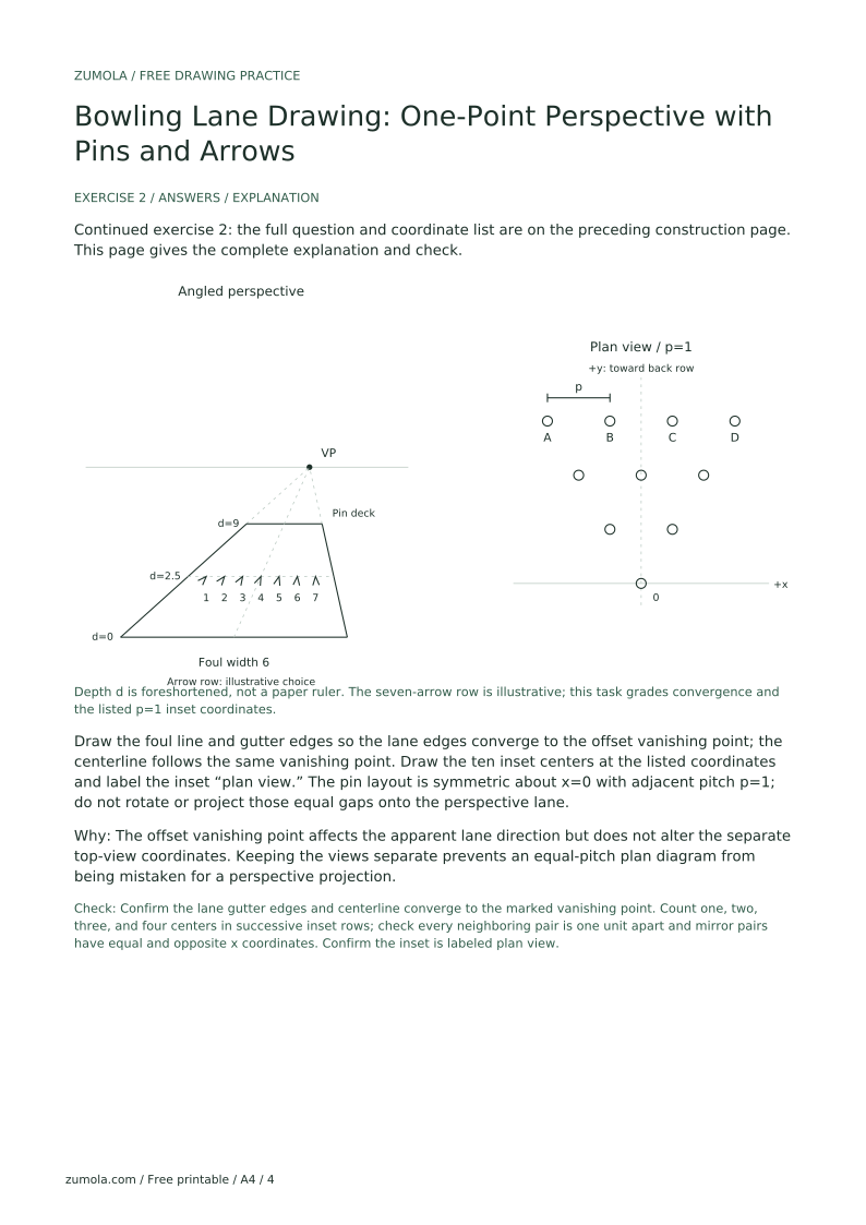
The offset vanishing point affects the apparent lane direction but does not alter the separate top-view coordinates. Keeping the views separate prevents an equal-pitch plan diagram from being mistaken for a perspective projection.
Check: Confirm the lane gutter edges and centerline converge to the marked vanishing point. Count one, two, three, and four centers in successive inset rows; check every neighboring pair is one unit apart and mirror pairs have equal and opposite x coordinates. Confirm the inset is labeled plan view.
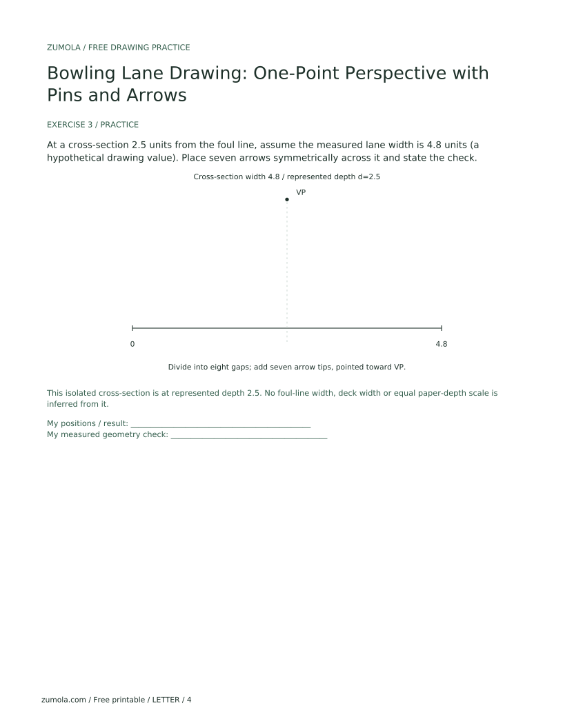
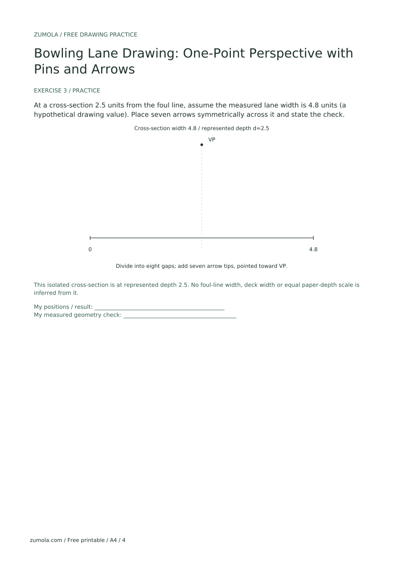
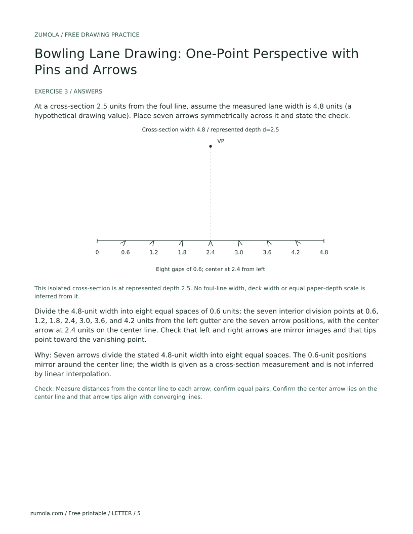
At a cross-section 2.5 units from the foul line, assume the measured lane width is 4.8 units (a hypothetical drawing value). Place seven arrows symmetrically across it and state the check.
Divide the 4.8-unit width into eight equal spaces of 0.6 units; the seven interior division points at 0.6, 1.2, 1.8, 2.4, 3.0, 3.6, and 4.2 units from the left gutter are the seven arrow positions, with the center arrow at 2.4 units on the center line. Check that left and right arrows are mirror images and that tips point toward the vanishing point.
Seven arrows divide the stated 4.8-unit width into eight equal spaces. The 0.6-unit positions mirror around the center line; the width is given as a cross-section measurement and is not inferred by linear interpolation.
Check: Measure distances from the center line to each arrow; confirm equal pairs. Confirm the center arrow lies on the center line and that arrow tips align with converging lines.
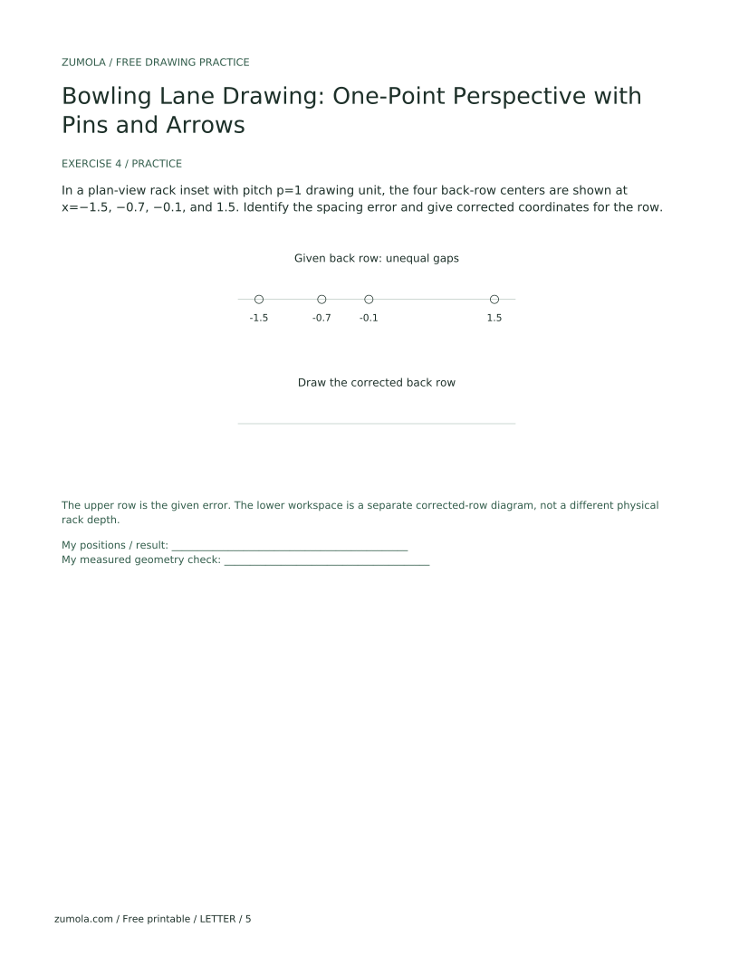
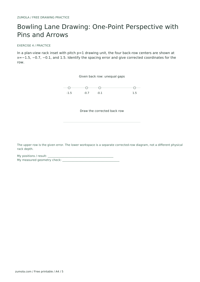
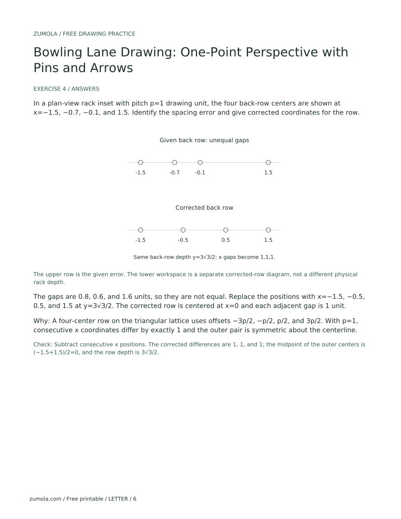
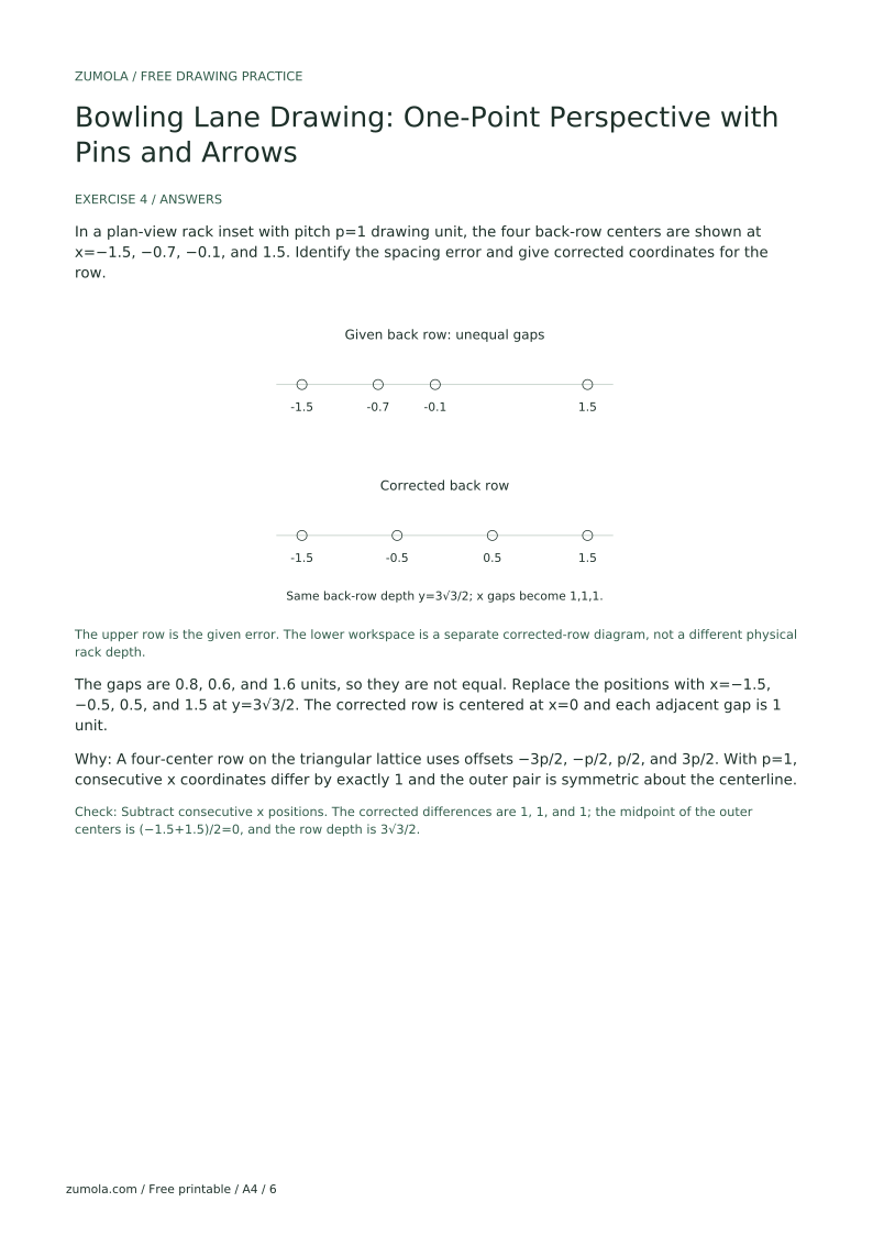
In a plan-view rack inset with pitch p=1 drawing unit, the four back-row centers are shown at x=−1.5, −0.7, −0.1, and 1.5. Identify the spacing error and give corrected coordinates for the row.
The gaps are 0.8, 0.6, and 1.6 units, so they are not equal. Replace the positions with x=−1.5, −0.5, 0.5, and 1.5 at y=3√3/2. The corrected row is centered at x=0 and each adjacent gap is 1 unit.
A four-center row on the triangular lattice uses offsets −3p/2, −p/2, p/2, and 3p/2. With p=1, consecutive x coordinates differ by exactly 1 and the outer pair is symmetric about the centerline.
Check: Subtract consecutive x positions. The corrected differences are 1, 1, and 1; the midpoint of the outer centers is (−1.5+1.5)/2=0, and the row depth is 3√3/2.
Extend both gutter lines to the vanishing point; if they do not meet, adjust the foul-line endpoints or vanishing point.
Use the plan-view coordinate formulas with x=0 as the symmetry axis. Check the stated pitch between neighboring centers instead of guessing equal row intervals from an unspecified outer boundary.
Keep arrows small and draw their tips along lines that converge at the vanishing point; check symmetry across the center line.
State the represented depth labels and the illustration's transverse width units separately. Use the foreshortened guide for depth positions; do not treat depth labels as equal ruler intervals on the printed centerline.
No. The lesson uses hypothetical proportions to teach perspective. Measure your drawing surface and keep relative positions consistent; exact real-world dimensions are not required.
Yes. Offset the vanishing point from the center of the foul line; gutter edges and the lane centerline still converge to it. Put the pin rack in a separately labeled plan-view inset beside the lane drawing, rather than rotating or projecting equal top-view gaps onto the perspective deck.
The supplied worksheet examples use seven arrows, following the count described in the cited USBC coaching guide. A separately stated drawing variation may use another symmetric count, but that is a drawing exercise, not a claim about equipment compliance.
In the plan-view inset, compare every adjacent pin-center gap with the stated pitch p; those gaps should remain equal. The inset is not projected, so it does not shrink with distance. Check lane foreshortening only on the perspective lane itself.
The equipment facts above were checked against USBC, Equipment Specifications and Certifications Manual (March 2026), Pin Spots, printed page 38; and the USBC High School Bowling Coaching Guide, printed page 11. The first describes the ten-spot equilateral arrangement; the second describes seven lane arrows. The single transverse arrow row, even projected gaps and drawing-unit values in this lesson are worksheet choices, not equipment-compliance specifications.