Free printable resources · Original practice
Three-point perspective.
Let verticals converge too.
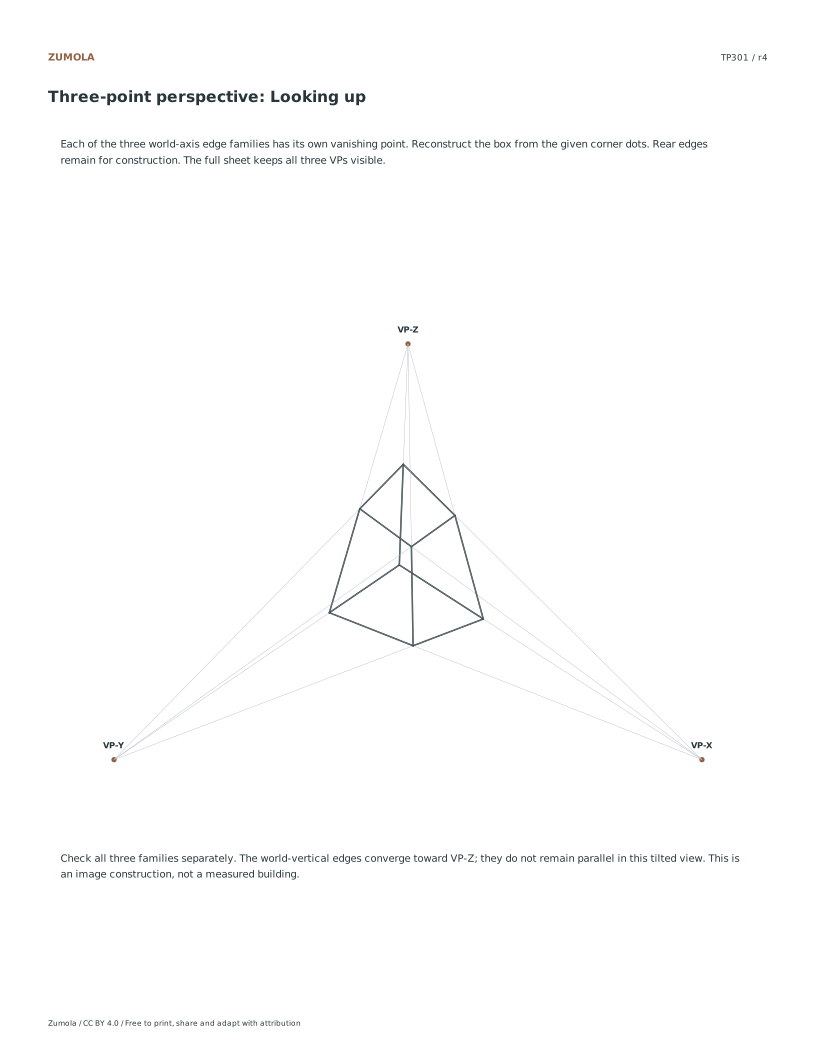
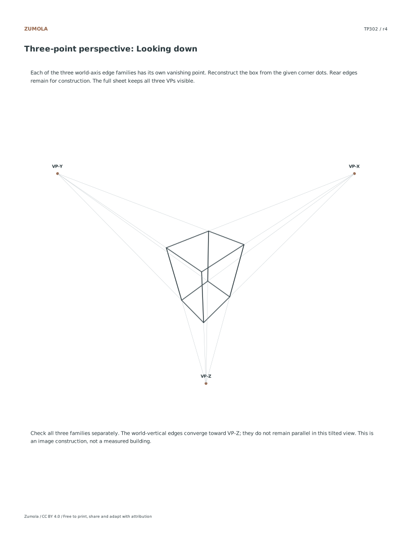
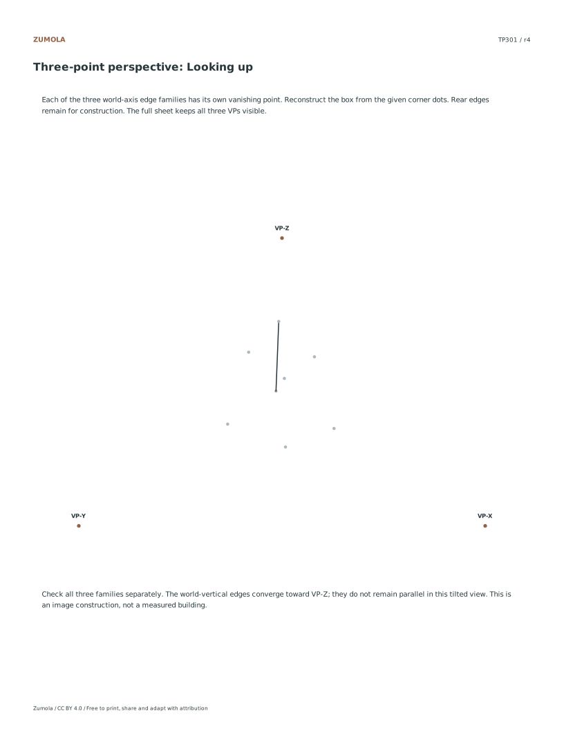
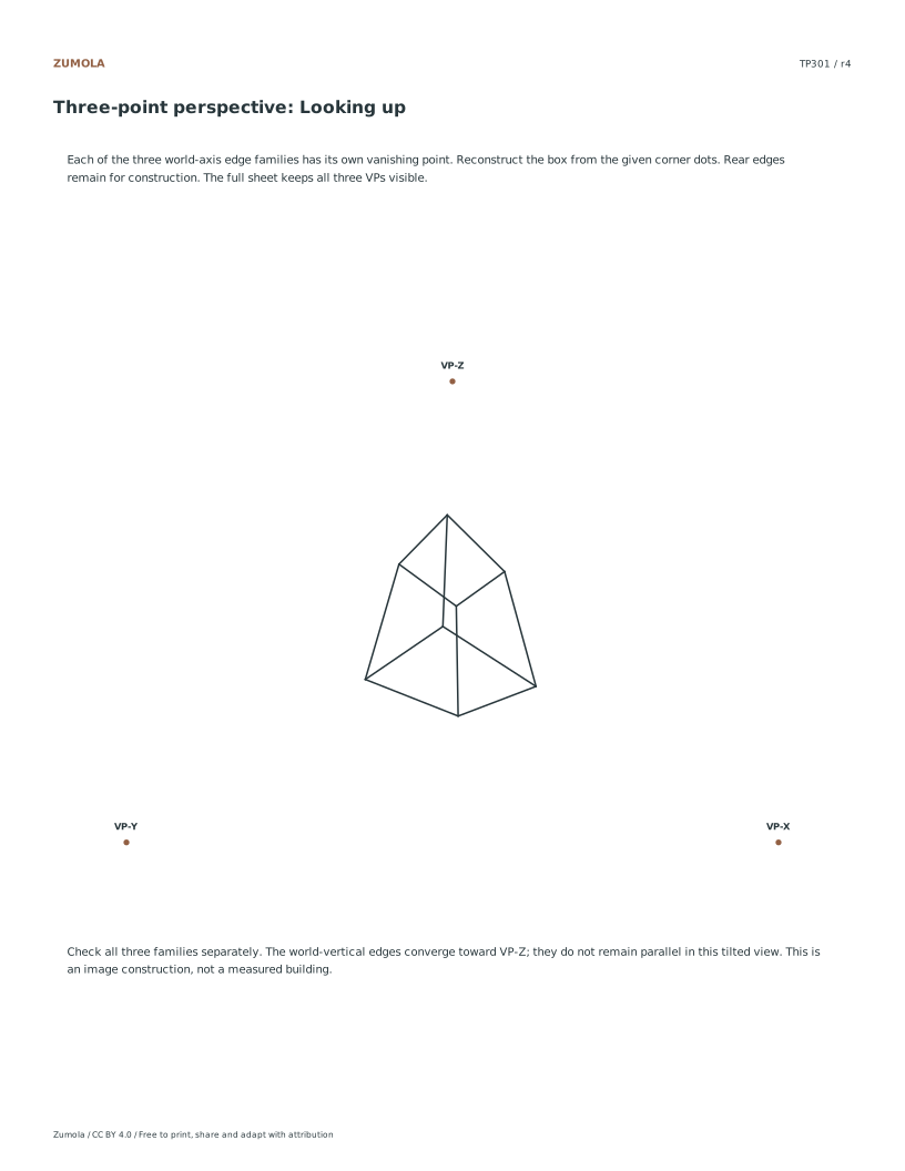
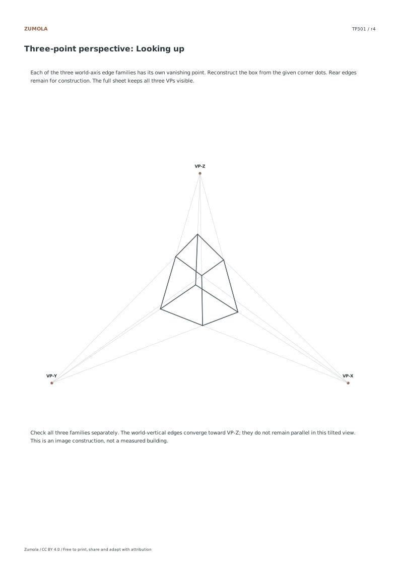
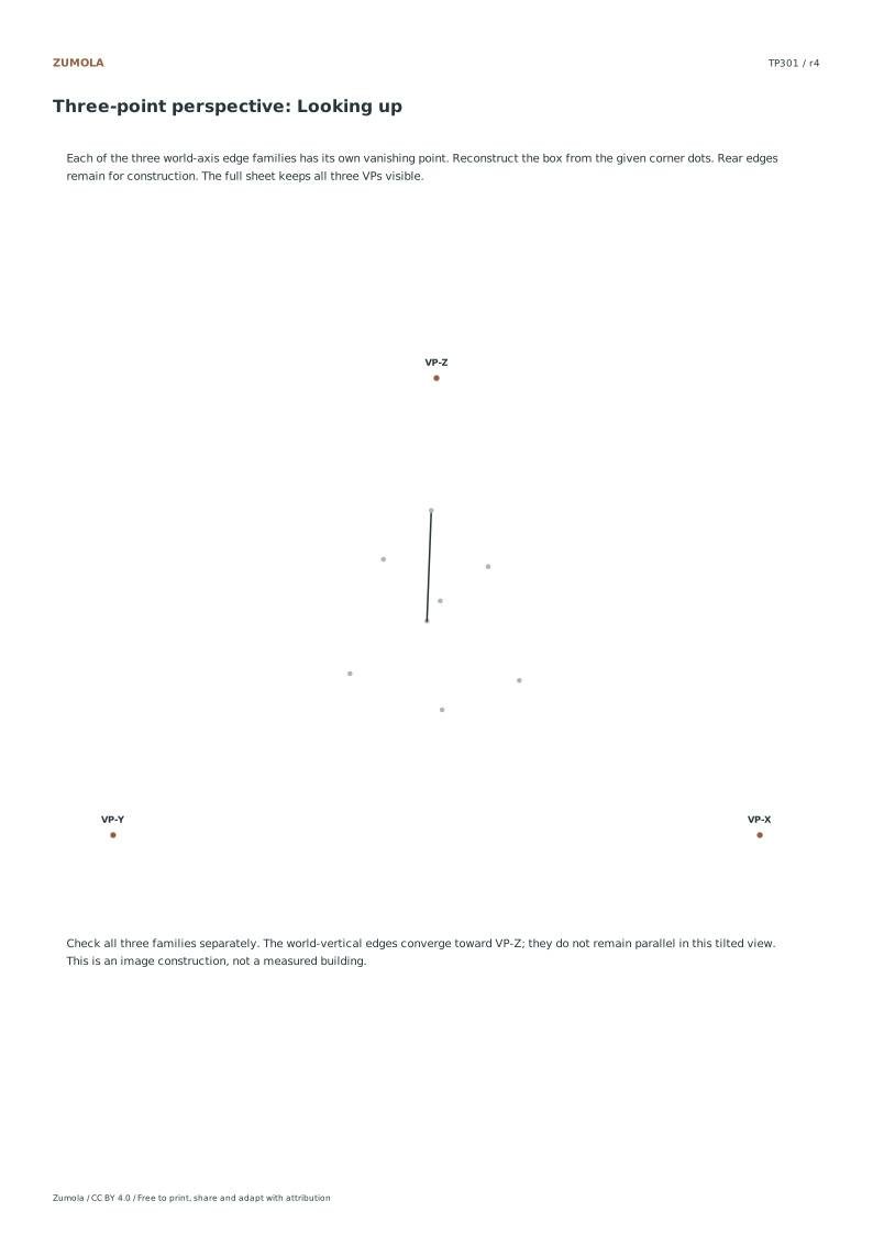
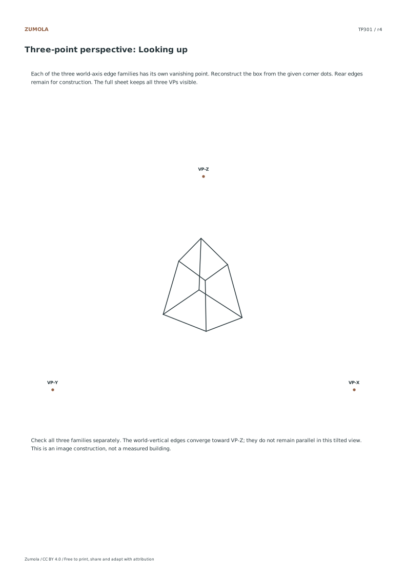
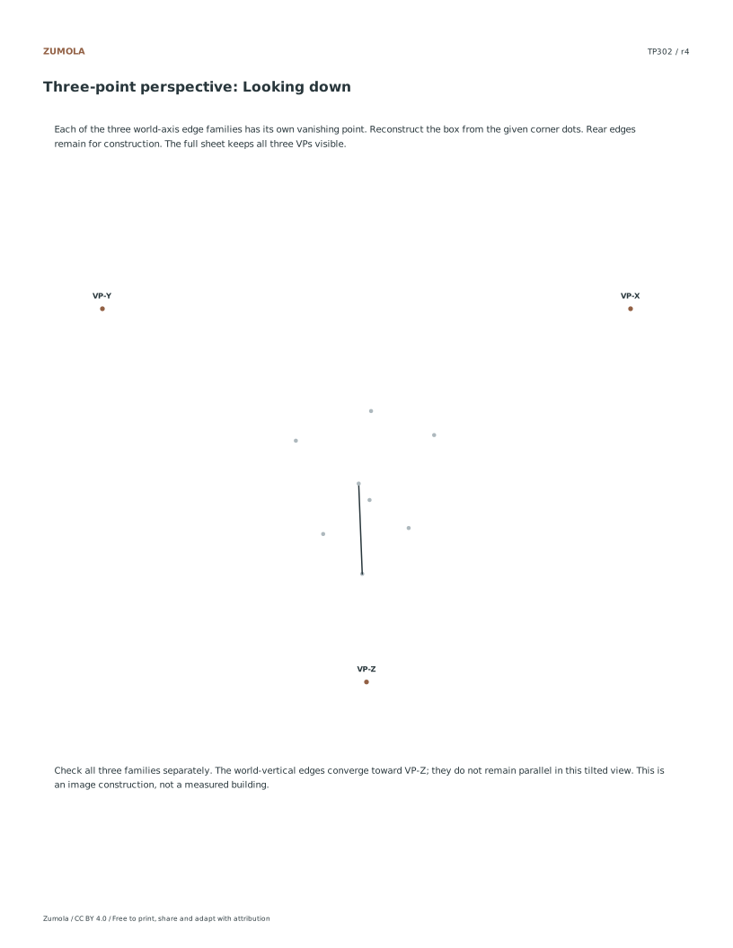
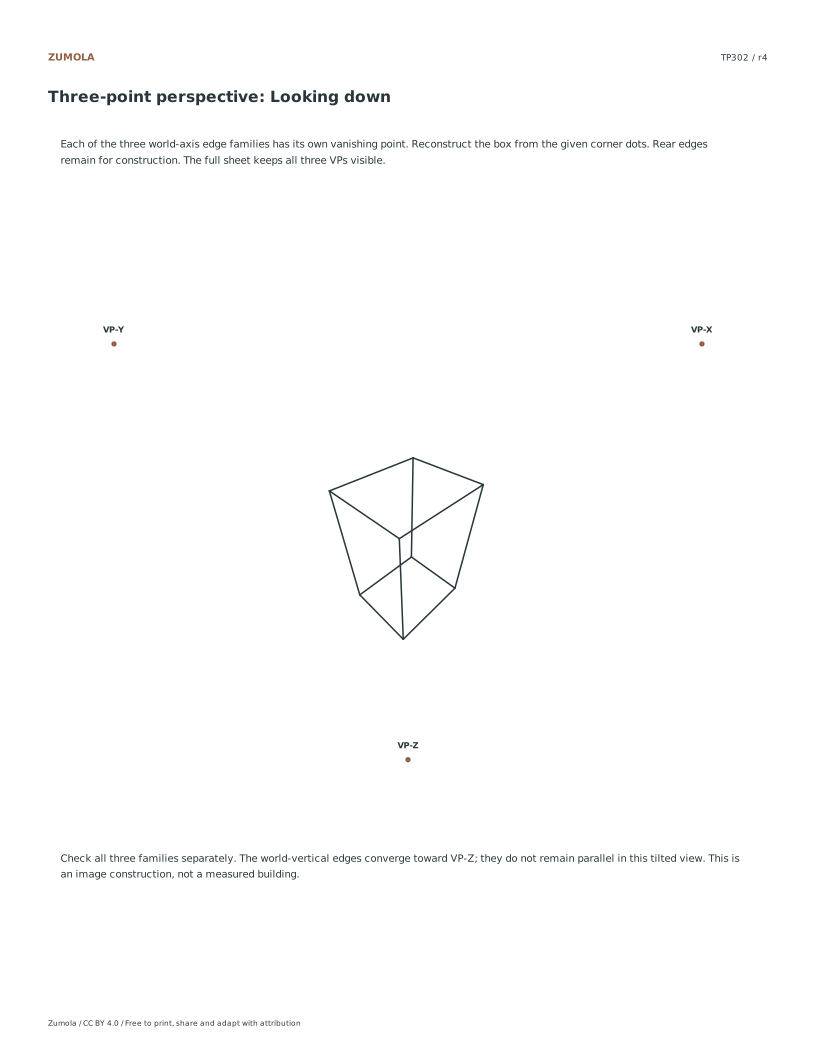
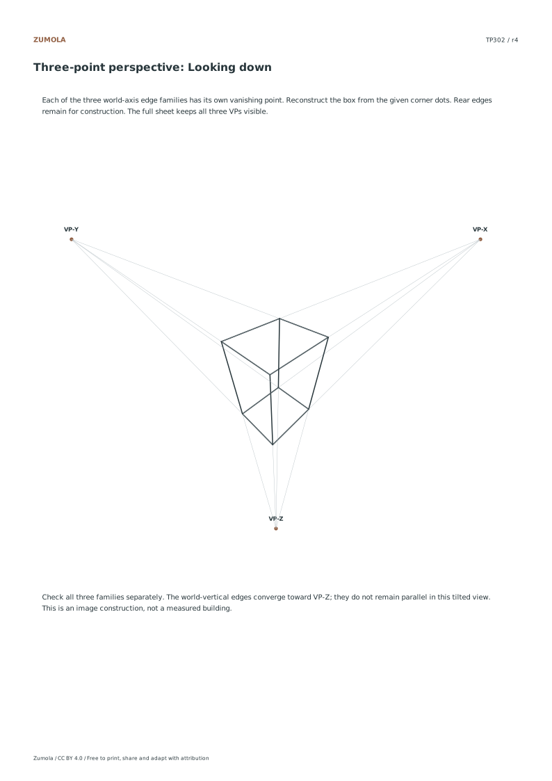
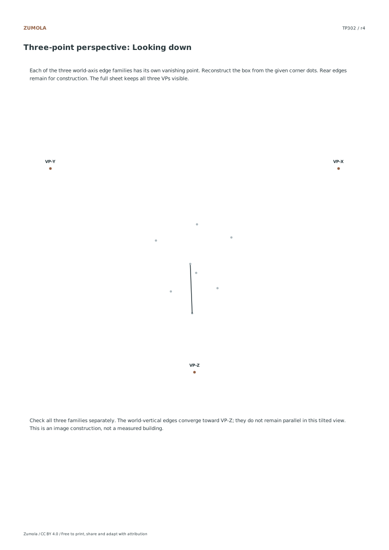
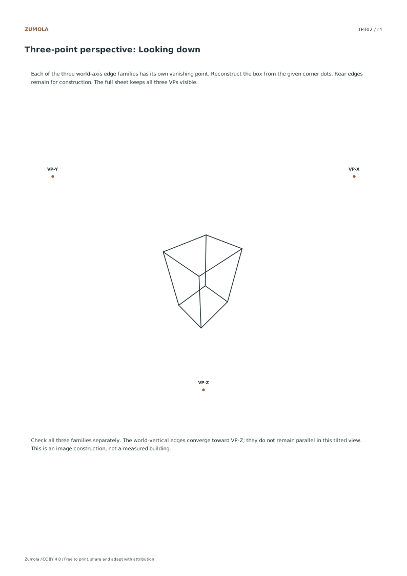
Tilt the view and follow three converging edge families. Reconstruct two original box studies from fixed corners and vanishing points.
Looking up & looking down.
Guides + student sheets + answers.
Print a test sheet before the full pack
Choose the file matching the paper in your printer. Print the PDF at Actual size / 100%, turning off Fit, Shrink and browser headers. An SVG editor or browser can change its scale even though the file uses millimeter dimensions. Use the supplied calibration bars where present when a task depends on physical size; a screen preview alone does not establish printed size.
The packs contain the same individual pages in collection order. They are a convenient download, not extra different exercises. On coordinate plots, uniform scaling preserves the numerical positions relative to the axes. On image-copy tasks, keep the specified proportions and any stated source-to-target enlargement. Color is optional: labels, line positions and relative lightness also explain the references.
More ways to practice
A second box with fixed coordinates
Work on a level horizon for this exercise. Use Cartesian coordinates with y pointing up, so the horizon is the line y = 0. Place the left vanishing point at L = (-10, 0), the right vanishing point at R = (10, 0), and the third vanishing point above the horizon at V = (0, 20). This is an unrolled drawing with a level horizon; a rolled camera could tilt the horizon without breaking perspective, so apply only the checks that match this setup.
The near vertical edge runs from A = (0, 4) to B = (0, 8). Choose the far lower left corner C = (-4, 2.4). Its upper partner D is the intersection of the line from C to V and the line from B to L, giving D = (-10/3, 16/3). Mirror C and D across x = 0 to get the right face. The construction is a wireframe: draw the lines first, then judge the solid.
- Mark L, R and V, then draw the horizon through L and R only.
- Draw the near vertical edge AB between y = 4 and y = 8 at x = 0.
- Place C at (-4, 2.4) and draw the line from C toward V.
- Draw the line from B toward L; where it crosses the C-to-V line is D.
- Mirror C and D across the vertical centre line to complete the right face.
- Check that A, C and L lie on one straight line, and that B, D and L do too.
Diagnostic checks that catch drift
The strongest check is line incidence. In this construction A, C and L must be collinear; B, D and L must be collinear; and C, D and V must be collinear. If any three points miss a common line, the error is in the construction, not in the shading. Check the mirrored right face the same way against R.
Do not decide whether the top or bottom face is visible only from whether V sits above or below the horizon. The object's position relative to eye level also matters, so a third vanishing point above the horizon does not by itself prove you are looking up at this box. Likewise, do not treat a near-versus-far edge length difference as a universal test for looking up or down. In this example the near segment AB has length 4, while CD is about 3.008; those numbers describe this chosen construction only. Use convergence as the diagnostic.
- Lay a straight edge along A and C and confirm it passes through L.
- Repeat for B and D against L, then for C and D against V.
- Check the mirrored corners against R in the same way.
- If a line misses, redraw from the fixed coordinates rather than nudging one corner.
Judging the result with a rubric
Art has multiple valid outcomes, so judge the drawing against criteria rather than a single correct picture. A clean wireframe with consistent convergence can still be shaded in several ways. Keep the geometric checks separate from the artistic choices, and note where a deliberate variation departs from the fixed coordinates.
- Confirm all three edge families converge to their assigned vanishing points.
- Confirm the horizon is level and L, R and V are marked once.
- Confirm the near vertical edge stays vertical in this unrolled setup.
- Note any shading or line-weight choices and whether they support the tilted view.
Try this example
Given L = (-10, 0), R = (10, 0), V = (0, 20), A = (0, 4), B = (0, 8) and C = (-4, 2.4), find D and state the three collinearity checks.
Show the worked explanation
D is the intersection of the line through C and V with the line through B and L, giving D = (-10/3, 16/3). The checks are: A, C and L are collinear; B, D and L are collinear; C, D and V are collinear. Mirroring C and D across x = 0 completes the right face, checked against R.
Common mistakes
- Assuming the top face must be visible because V is above the horizon. Check the box's position relative to eye level as well; V position alone does not decide face visibility.
- Using near and far edge lengths as a universal test for looking up or down. Use line incidence against the vanishing points instead; lengths here describe only this construction.
- Nudging a single corner to make the drawing look right. Redraw from the fixed coordinates so A, C and L stay collinear and B, D and L stay collinear.
Check your work
- All three edge families converge to their assigned vanishing points.
- A, C and L are collinear, and B, D and L are collinear.
- C, D and V are collinear, with the mirrored corners checked against R.
- The horizon is level and the vanishing points are marked once.
- Face visibility is judged from object position and eye level, not V position alone.
Questions before you start
Why is D not simply placed by eye?
D is defined as the intersection of the C-to-V line and the B-to-L line, so placing it by eye risks breaking both incidences at once.
Does a tilted horizon always mean the perspective is wrong?
No. A rolled camera can produce a tilted horizon without breaking perspective; the level horizon here is an assumption for this unrolled drawing.
What does the length comparison show?
Only that AB is 4 and CD is about 3.008 in this specific construction; it is not a general rule for diagnosing view direction.