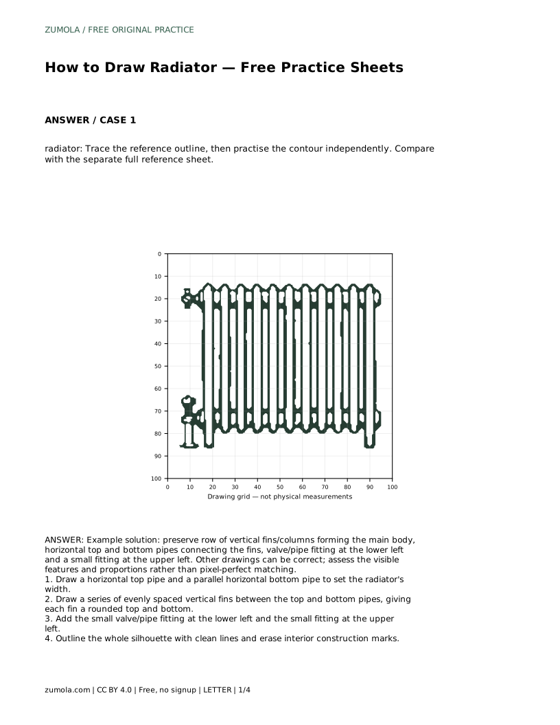
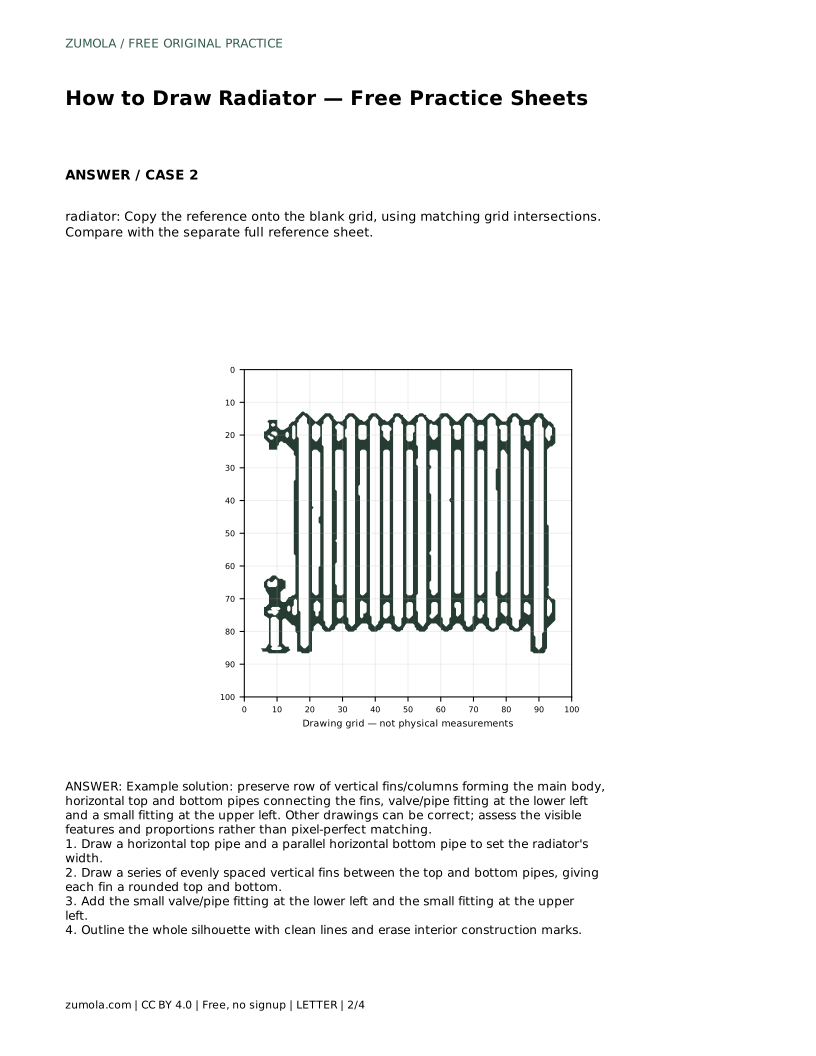
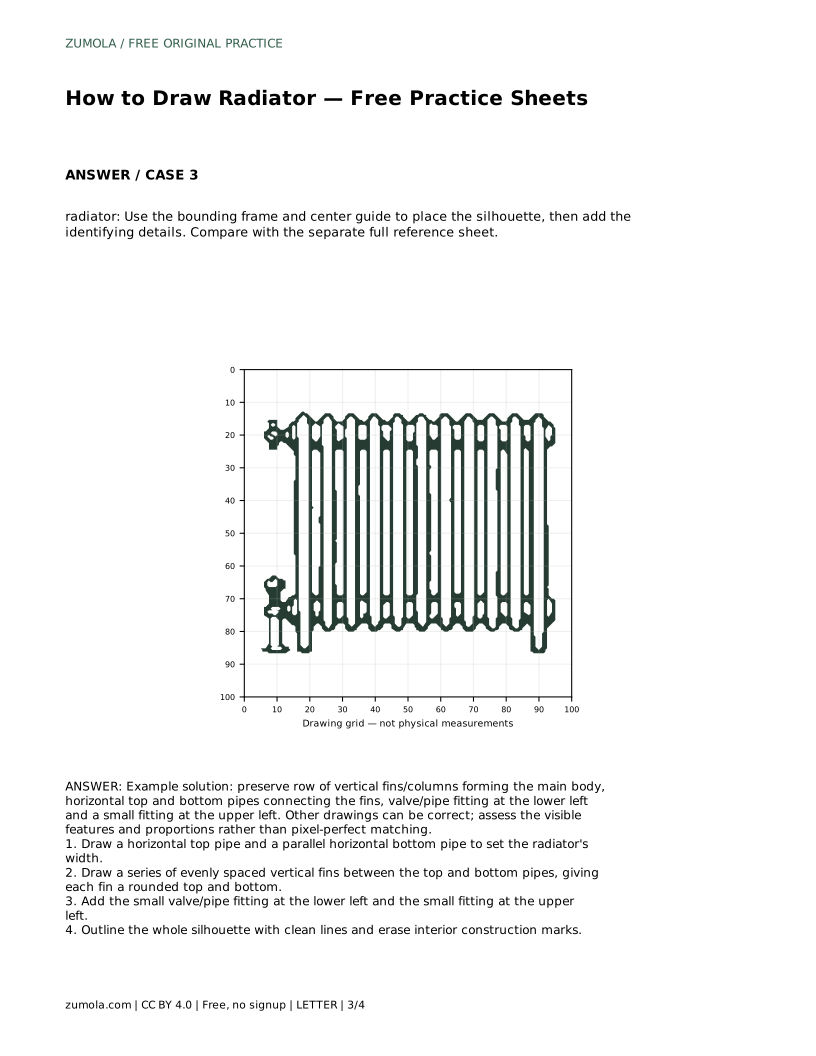
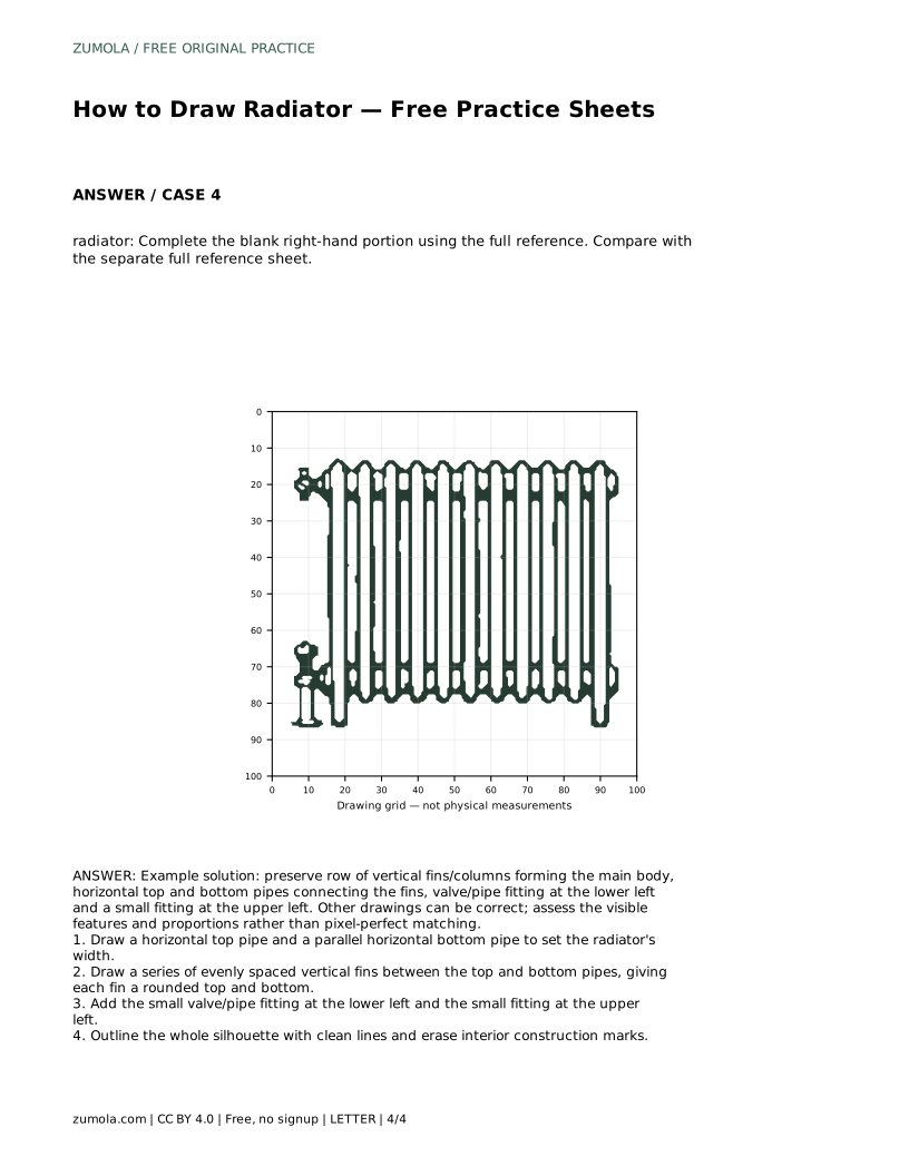
Reference diagrams
LETTER · Download PDF
A4 · Download PDF
Free original resources
Learn to draw a radiator by setting top and bottom pipes, spacing vertical fins evenly, and adding the lower-left valve and upper-left fitting.
Four original cases, with reference diagrams, practice sheets and worked answers. Everything is free; no signup required.
LETTER · Download PDF
A4 · Download PDF
LETTER · Download PDF
A4 · Download PDF
LETTER · Download PDF
A4 · Download PDF
Use A4 or US Letter to match your printer. Use the stated values and conditions to solve each exercise; diagrams are not physical measuring rulers.
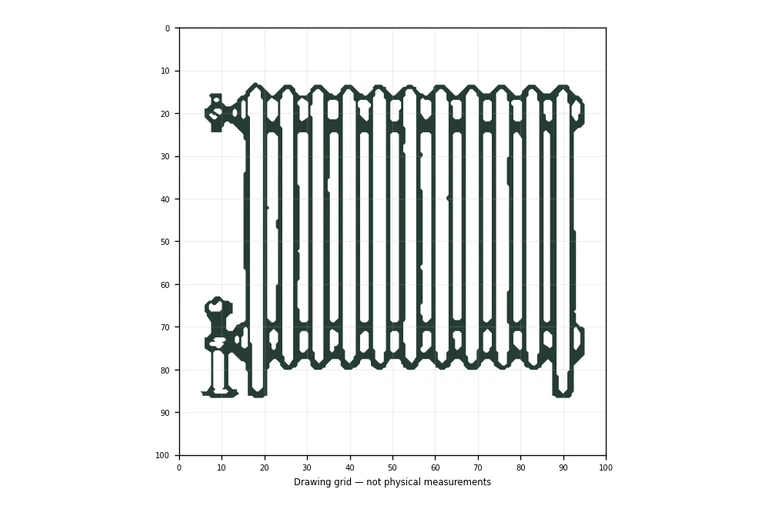
A radiator drawing is mostly a spacing problem. Once you fix the width with two horizontal pipes, the vertical fins need even gaps and consistent height, and the small fittings at the left side tell the viewer which end is which. This page explains a reliable order for building the shape, then shows how the same method works when you trace a reference, copy onto a grid, or complete a partly drawn sheet.
Start with the two horizontal pipes because they decide the overall width and the vertical span of the body. Draw the top pipe first, then a parallel bottom pipe below it. Keep the gap between them consistent along the whole length; if the pipes converge, every fin will inherit that error.
Next, divide the space between the pipes into evenly spaced vertical fins. Each fin runs from the top pipe to the bottom pipe and has a rounded top and bottom where it meets them. Count your fins before drawing so the spacing stays regular, and check that the first and last fins sit at the ends of the pipes rather than floating inward.
The lower-left valve and the small upper-left fitting are the details that make the object read as a radiator rather than a row of bars. Place them after the fins, when the body's width and height are already settled, so they attach to the correct end of the pipes.
Finish by tracing the outer silhouette with clean lines and erasing the construction marks inside. Keep the fins visible as separate columns; merging them into a solid block loses the feature that identifies the object.
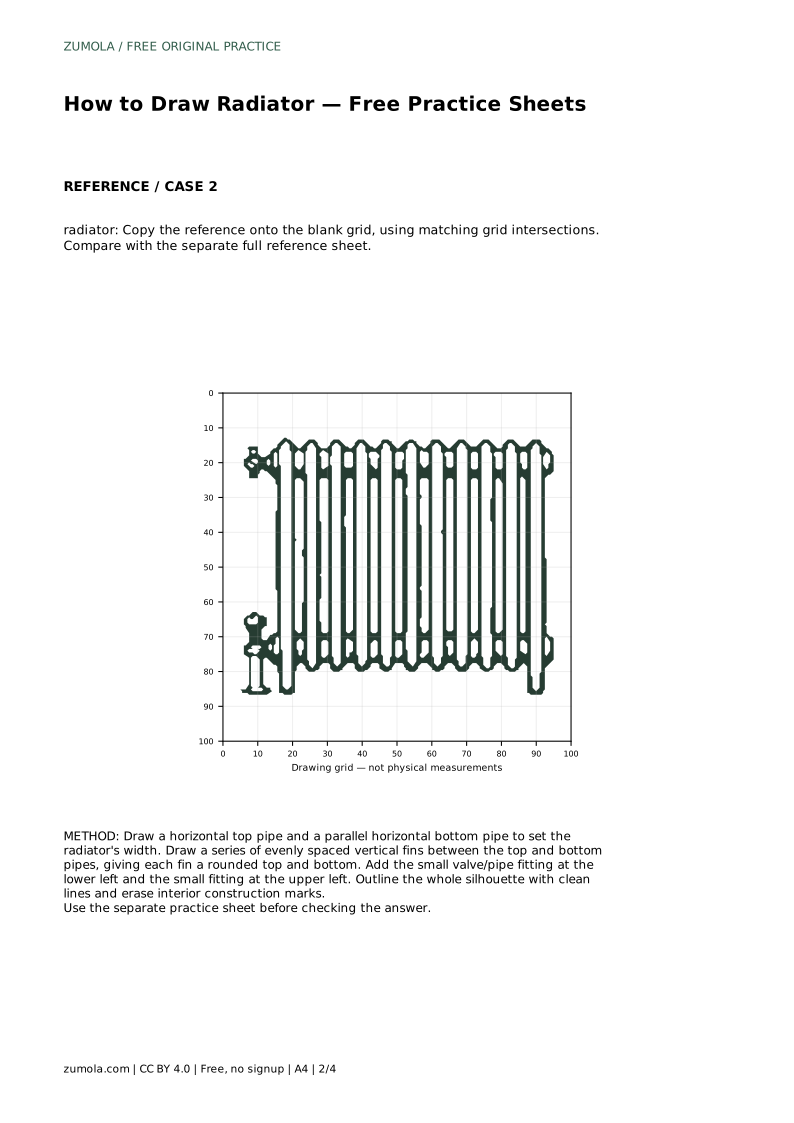
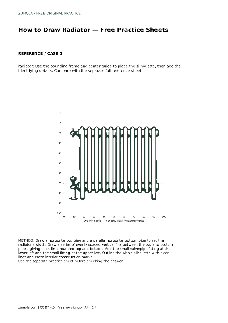
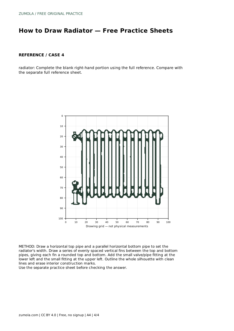
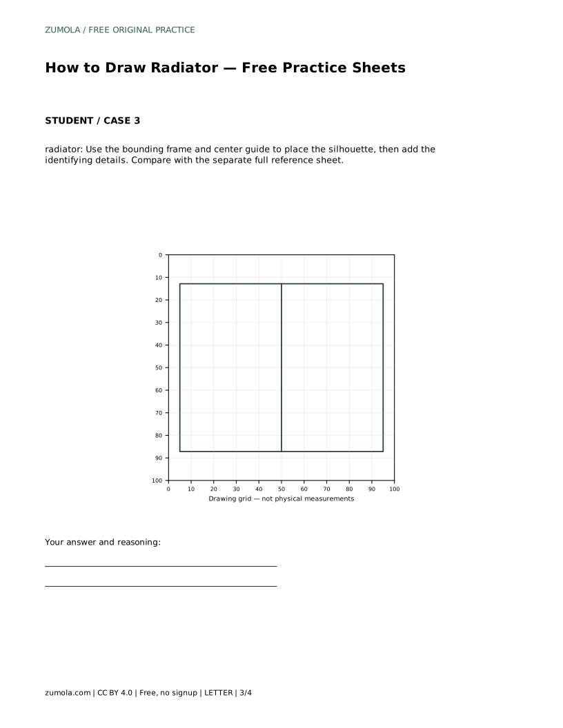
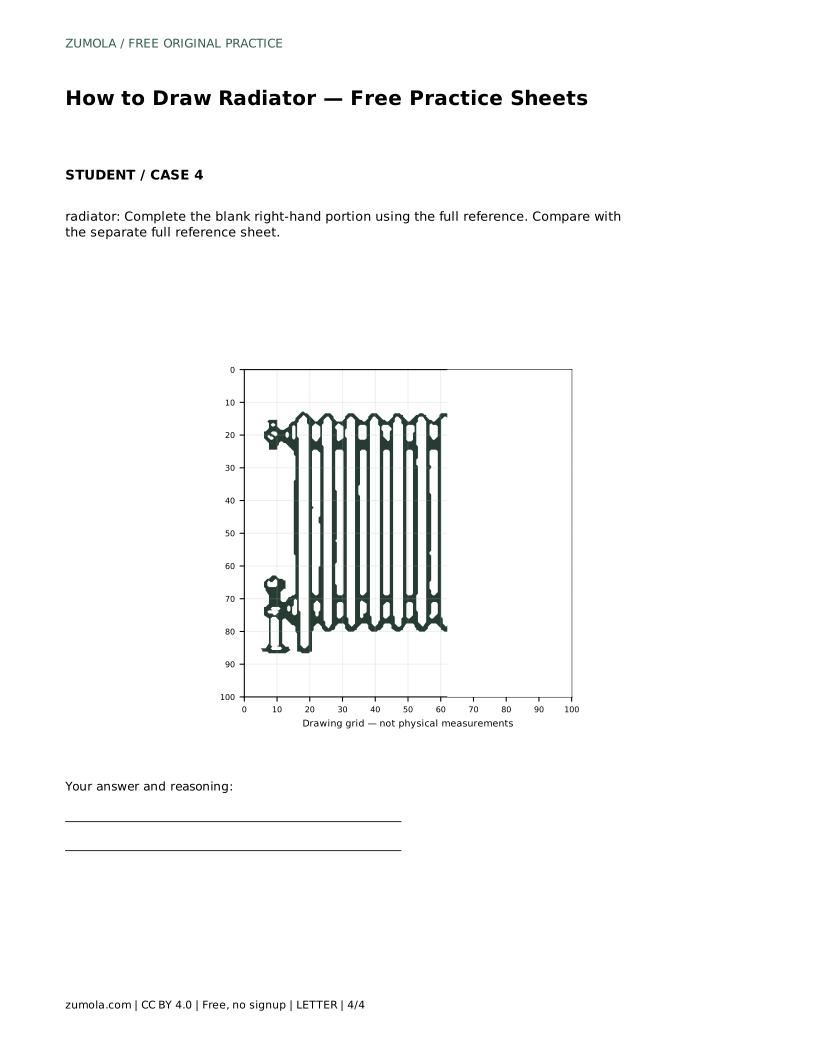
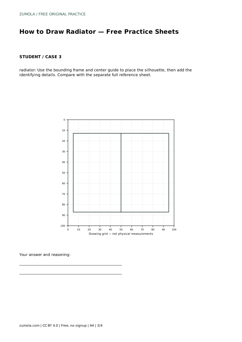
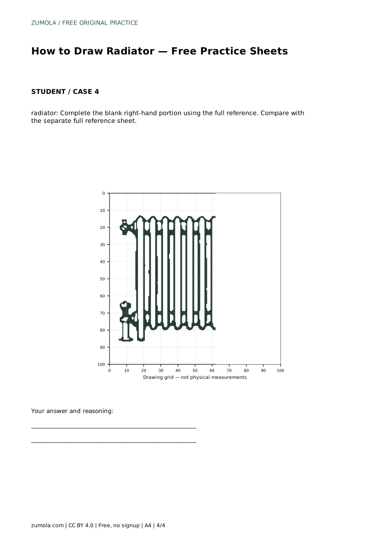
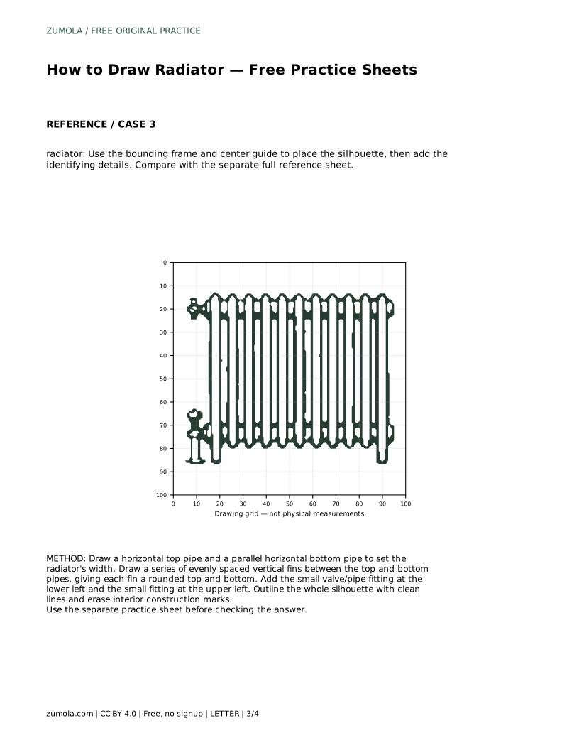
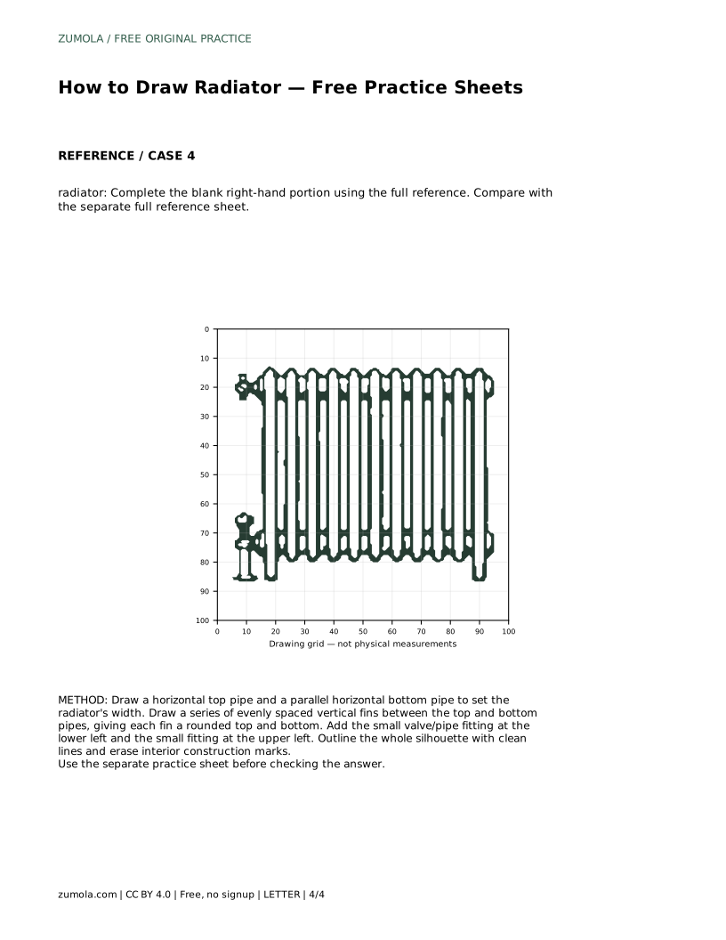
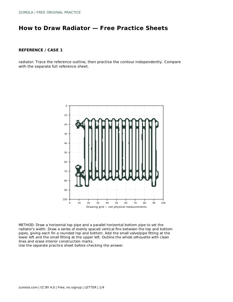
The trace sheet asks you to follow the reference outline first, then repeat the contour without it. The grid sheet asks you to copy the reference onto blank squares, matching grid intersections so proportions carry across. The bounding-frame sheet gives you an outer frame and center guide for placing the silhouette before adding details. The partial sheet leaves the right-hand portion blank, so you complete the fins and pipes using the full reference.
In every format, compare your drawing with the separate full reference sheet rather than judging from memory. Different drawings can be correct; assess the visible features and proportions rather than pixel-perfect matching.
Look at the drawing from a short distance. The pipes should read as parallel, the fins as a row of similar columns, and the two left-side fittings as distinct small shapes. If one fin is much wider than its neighbors, the spacing drifted; if the top pipe slopes, the whole body looks tilted.
Remember that this is a drawing exercise about observed shape, not a diagram of how heating systems work. The goal is a recognizable radiator with consistent proportions.
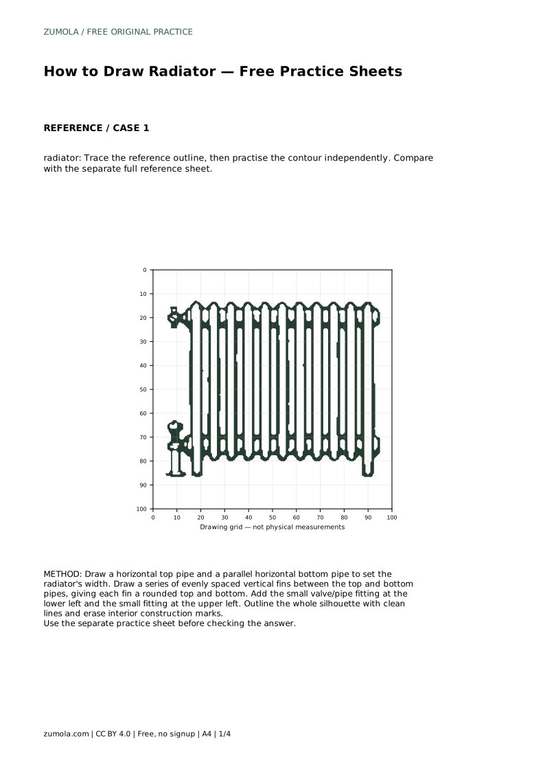
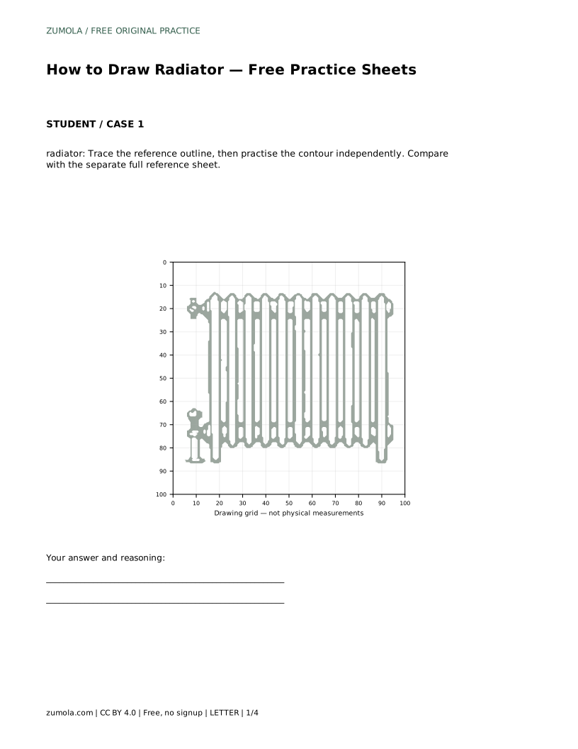
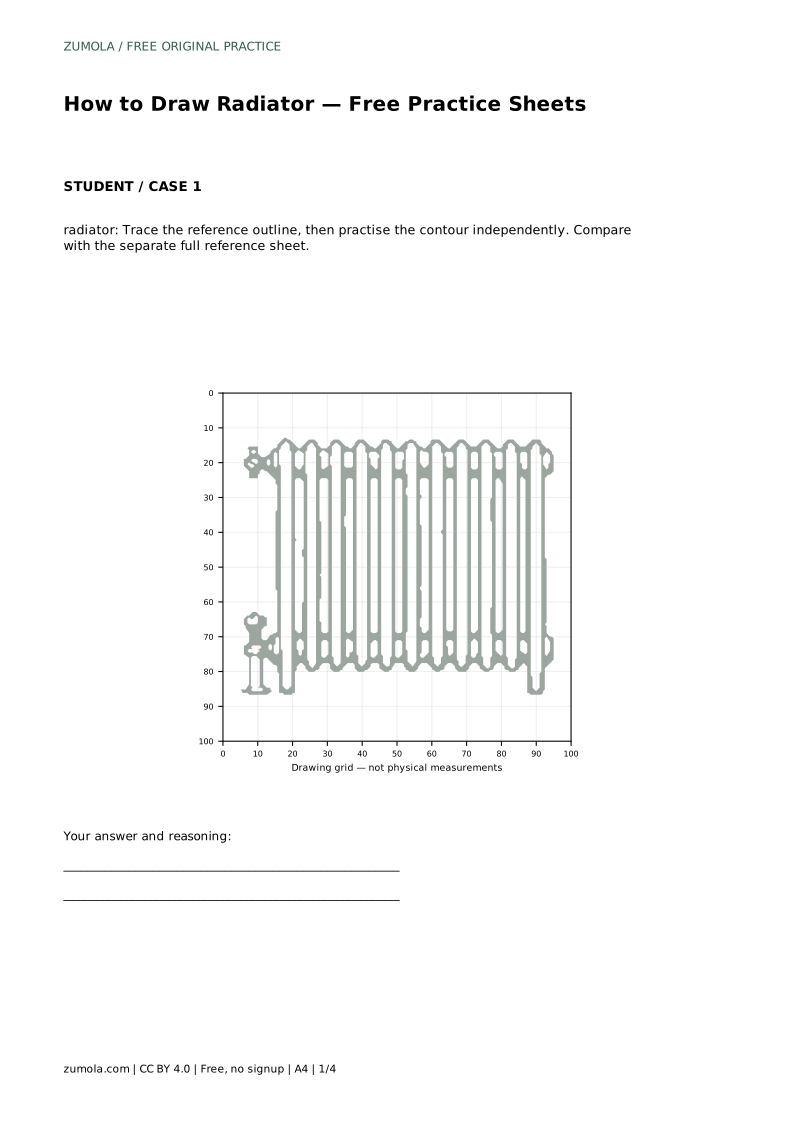
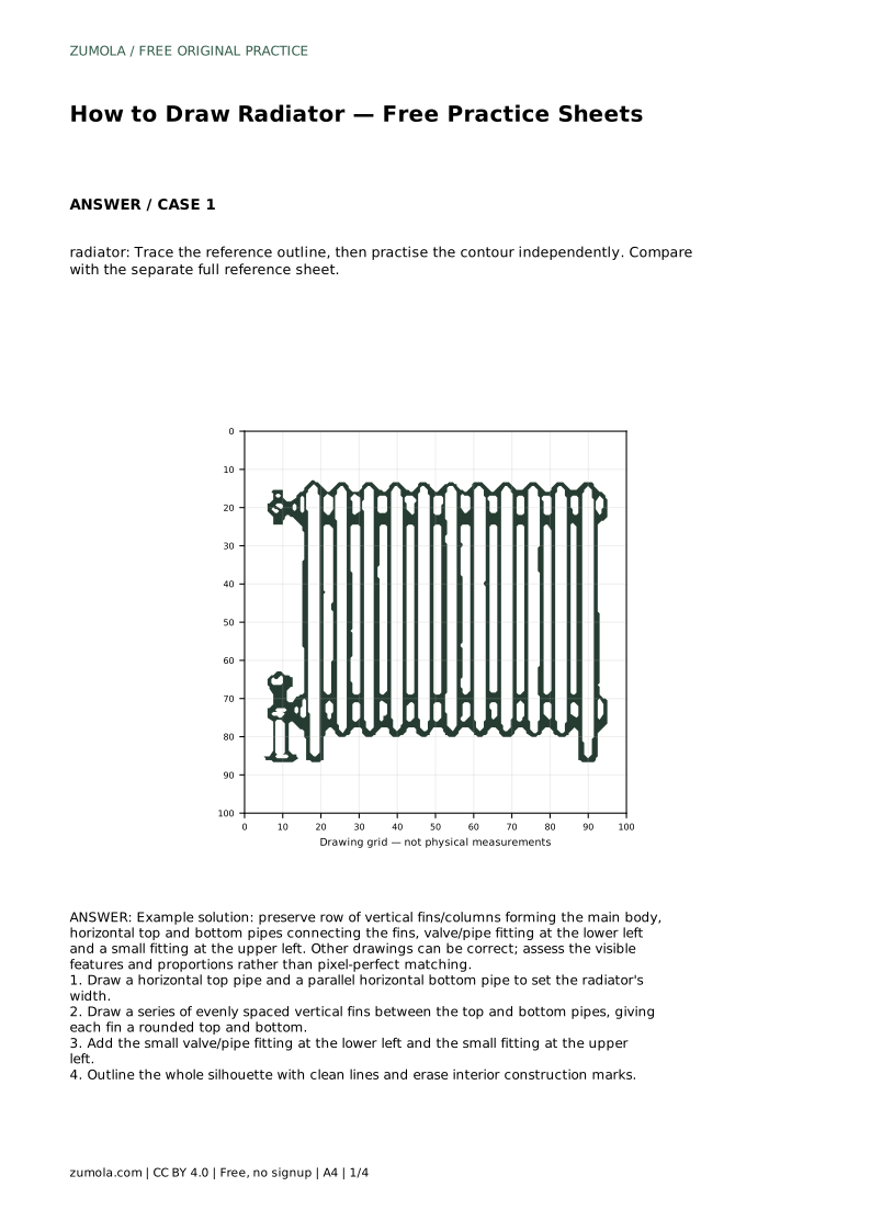
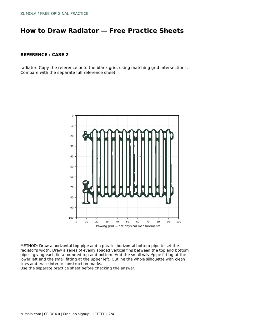
radiator: Trace the reference outline, then practise the contour independently. Compare with the separate full reference sheet.
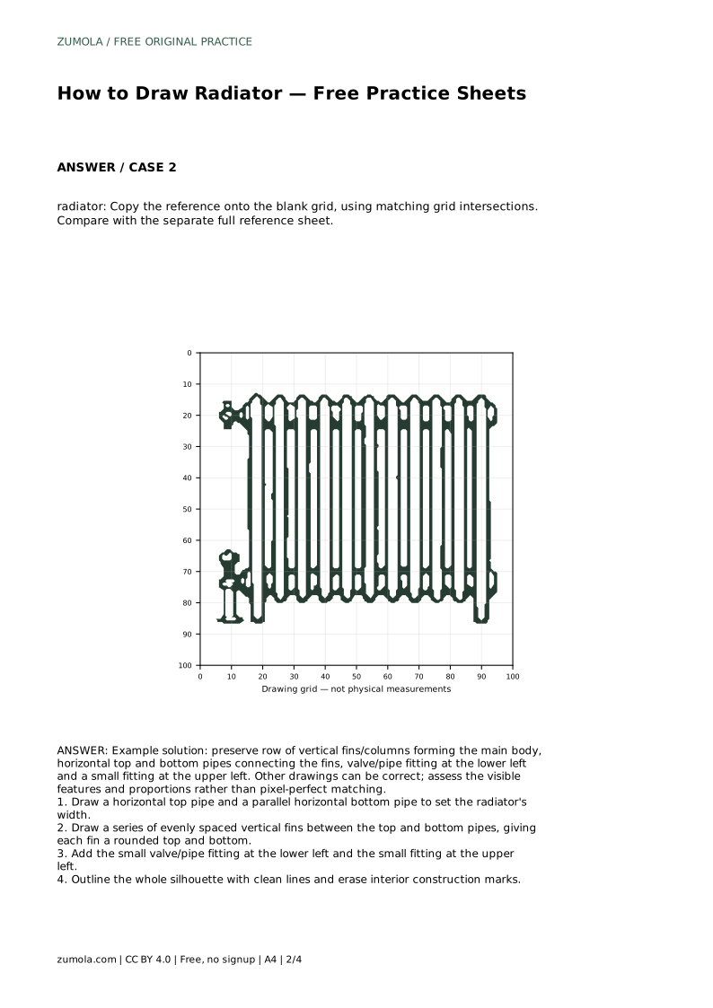
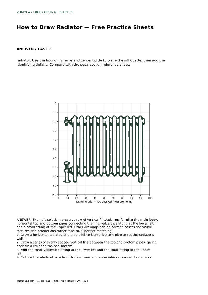
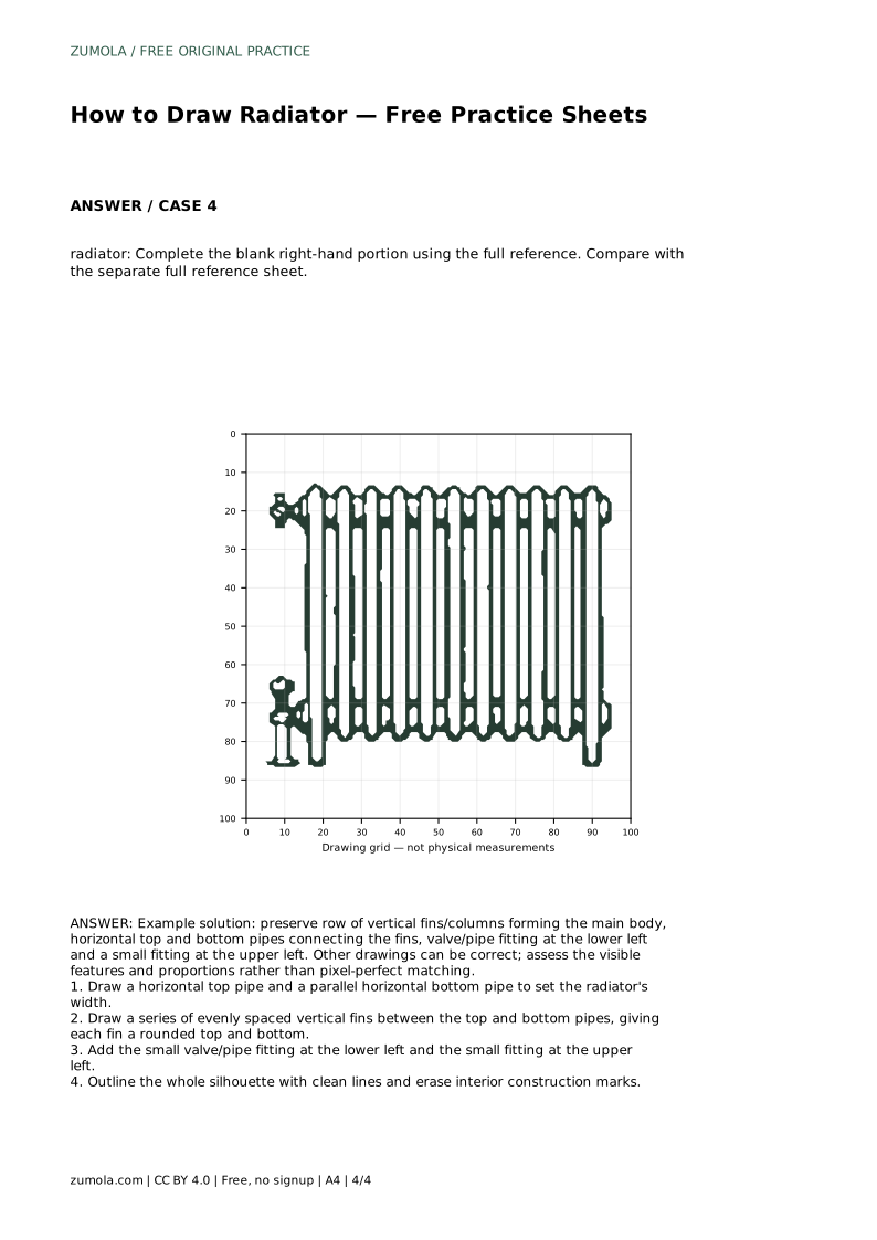
Example solution: preserve row of vertical fins/columns forming the main body, horizontal top and bottom pipes connecting the fins, valve/pipe fitting at the lower left and a small fitting at the upper left. Other drawings can be correct; assess the visible features and proportions rather than pixel-perfect matching. Draw a horizontal top pipe and a parallel horizontal bottom pipe to set the radiator's width. Draw a series of evenly spaced vertical fins between the top and bottom pipes, giving each fin a rounded top and bottom. Add the small valve/pipe fitting at the lower left and the small fitting at the upper left. Outline the whole silhouette with clean lines and erase interior construction marks.
They should look evenly spaced and similar in width. Small differences are acceptable, but a fin that is clearly wider or narrower than its neighbors breaks the row.
The valve or pipe fitting sits at the lower left, and the small fitting sits at the upper left. Both attach to the ends of the horizontal pipes.
Yes. The formats are separate practice options. The grid sheet works on its own if you match grid intersections carefully.
All drawing practice · Free coordinate paper
Original resources · CC BY 4.0 · Free for personal and classroom use with attribution.