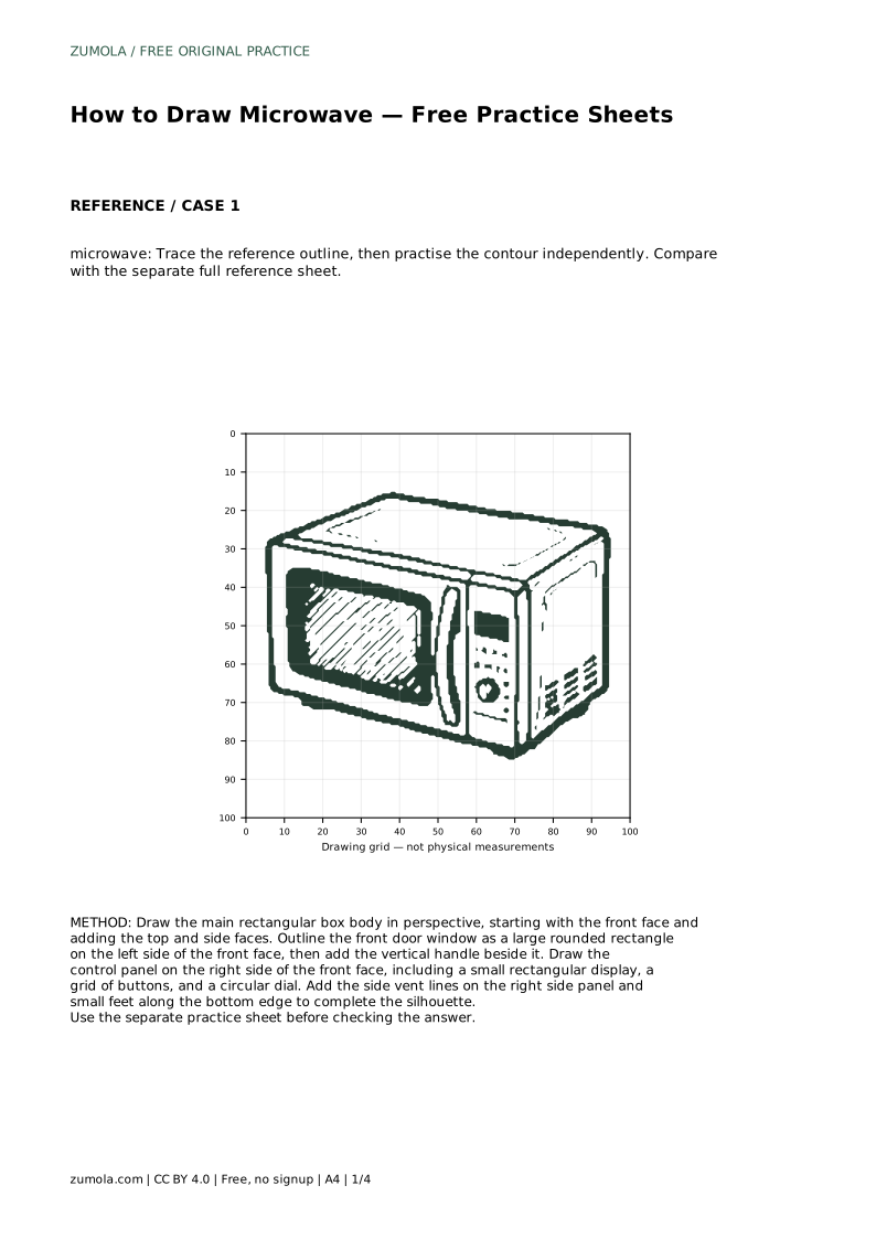
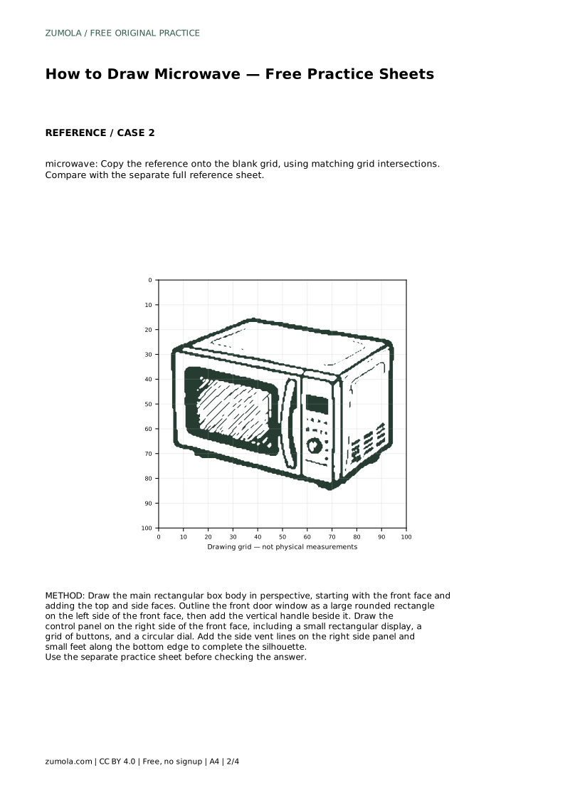
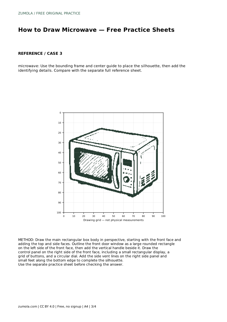
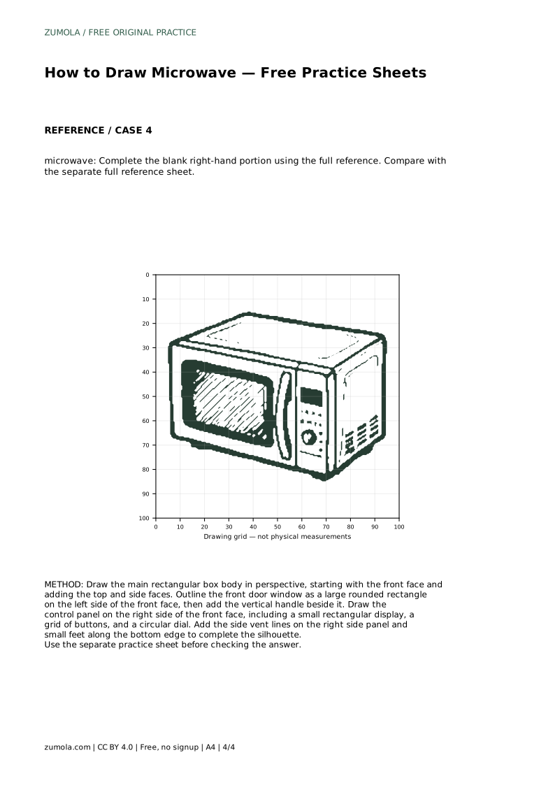
Reference diagrams
LETTER · Download PDF
A4 · Download PDF
Free original resources
Learn to draw a microwave in perspective with a clear door, handle, control panel, vents, and feet. Free printable practice sheets support tracing, grids, and guided placement.
Four original cases, with reference diagrams, practice sheets and worked answers. Everything is free; no signup required.
LETTER · Download PDF
A4 · Download PDF
LETTER · Download PDF
A4 · Download PDF
LETTER · Download PDF
A4 · Download PDF
Use A4 or US Letter to match your printer. Use the stated values and conditions to solve each exercise; diagrams are not physical measuring rulers.
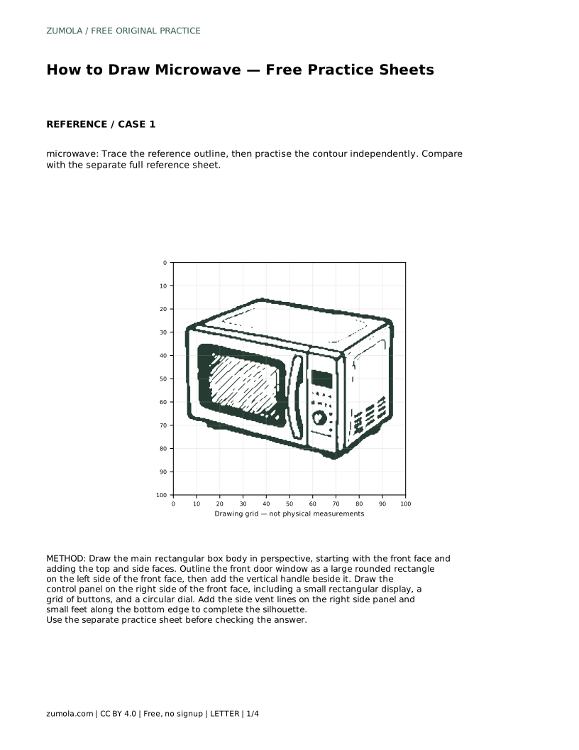
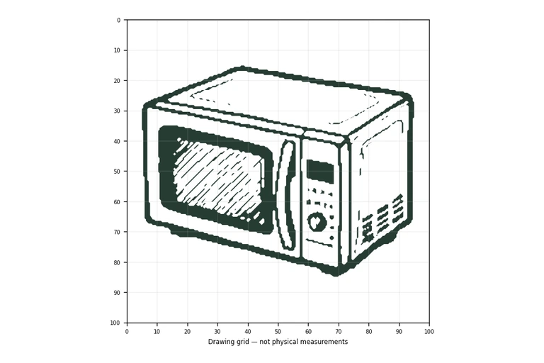
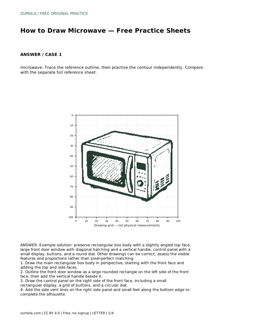
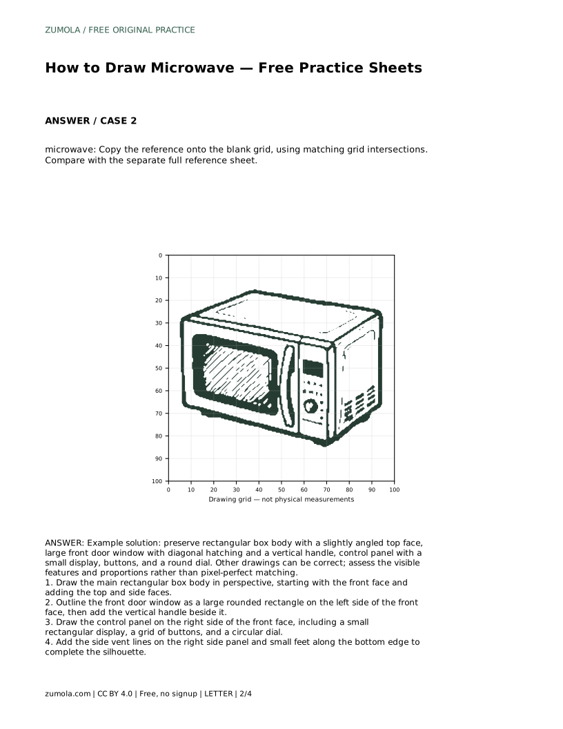
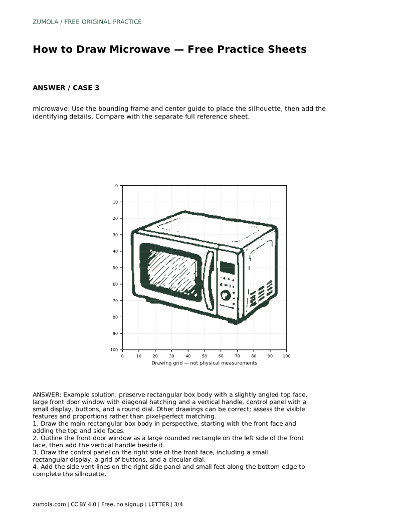
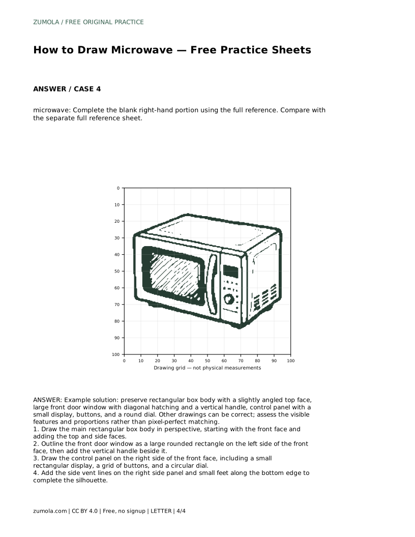
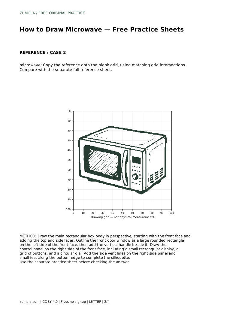
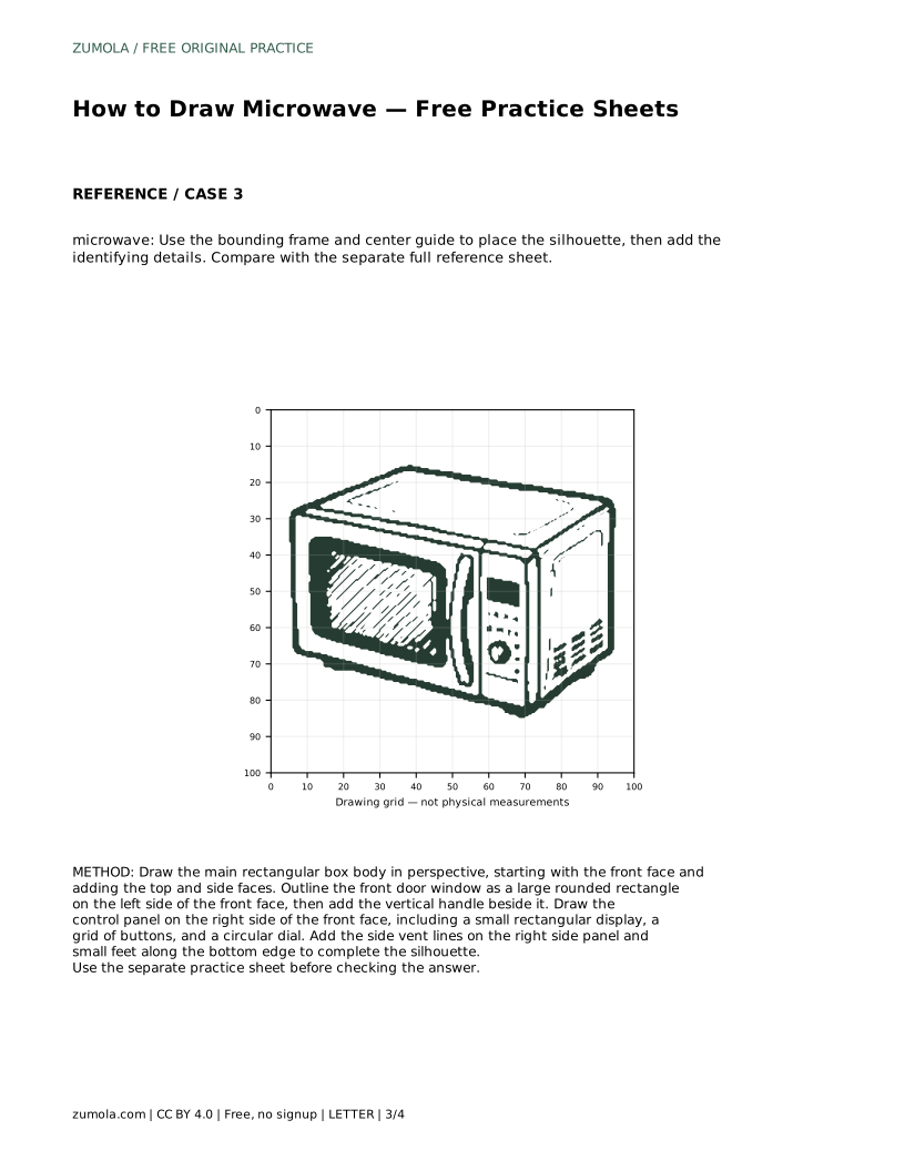
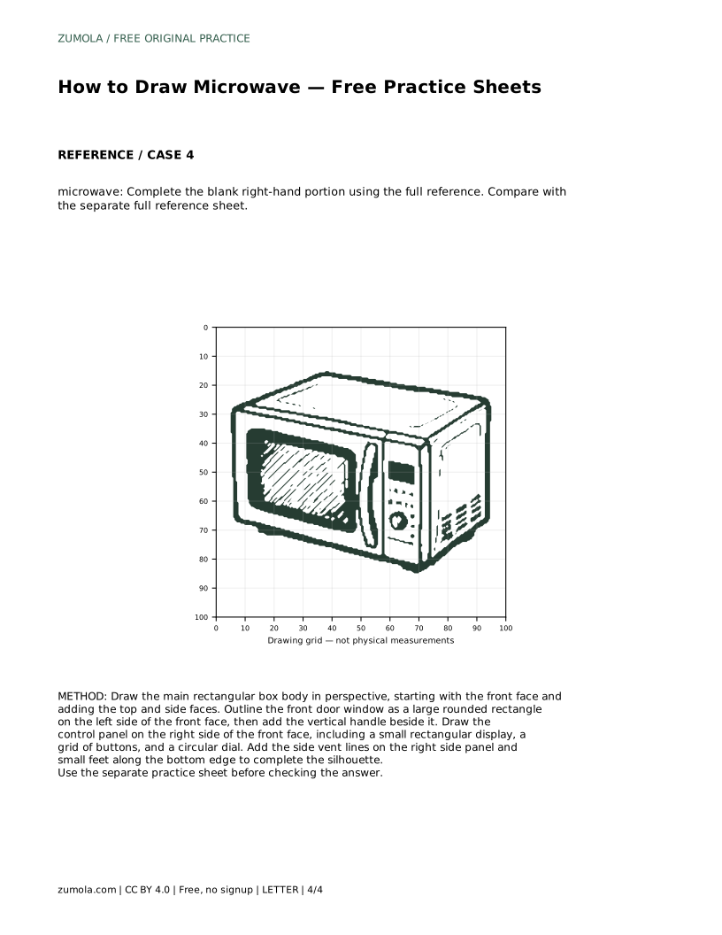
Drawing a microwave is a practical exercise in combining a boxy body with a busy front face. The goal is not a perfect copy but a recognizable appliance with believable proportions. This guide breaks the drawing into four stages: the main box in perspective, the door window and handle, the control panel, and the finishing details. Use the free practice sheets to trace, copy onto a grid, or complete a partially drawn version. Compare your work with the full reference sheet and judge the visible features rather than pixel-perfect matching.
A microwave is essentially a rectangular box, but drawing it flat makes it look like a plain rectangle. Begin with the front face as a large rectangle. Then add a top face that slopes slightly upward and back, and a narrow side face on the right. Keep the front face the largest area, because that is where the door and controls sit. The top and side faces should be narrower, suggesting depth without turning the drawing into a full architectural perspective.
Use light construction lines first. Check that opposite edges of the front face stay parallel, and that the top and side faces meet at consistent angles. The box does not need to be a perfect cube; most microwaves are wider than they are tall, so make the front face wider than its height. Leave space at the bottom for small feet.
The door window is the largest feature on the front face. Draw it as a large rounded rectangle on the left side, leaving a margin around it. The window should not touch the outer edges of the front face. Inside the window, add diagonal hatching lines to suggest the glass and the internal mesh. Keep the hatching evenly spaced and parallel; it is a texture, not a random scribble.
Beside the window, draw a vertical handle. The handle is usually a narrow rectangle or a rounded bar attached to the door. Place it on the right edge of the door, close to the control panel. Make sure the handle is vertical and does not overlap the window. Its height should be roughly half the window height, centered vertically.
The control panel occupies the right side of the front face. Start with a small rectangular display near the top of the panel. Below it, arrange a grid of buttons: two or three columns of small squares or circles. At the bottom of the panel, draw a round dial. The dial should be clearly circular, not oval, and sized to fit the panel width.
Keep the control panel elements aligned. The display, buttons, and dial should share a vertical center line. Leave a small gap between the door handle and the panel so the two features do not merge. If the panel feels crowded, simplify the button grid to a few representative buttons rather than many tiny ones.
On the right side face, add a few short horizontal lines to suggest ventilation slots. These lines should be parallel and evenly spaced, and they should not extend onto the front face. Along the bottom edge of the front face, draw two small feet: short rectangles or trapezoids that lift the box slightly off the ground. The feet should be placed near the left and right corners.
Finally, review the drawing against the reference. Check that the box body has a visible top and side face, the window is large and hatched, the handle is vertical, the control panel has a display, buttons, and a dial, and the side vents and feet are present. Adjust proportions if the window looks too small or the control panel too wide. Remember that multiple valid drawings exist; assess the visible features and overall balance rather than exact matching.
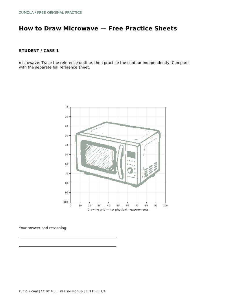
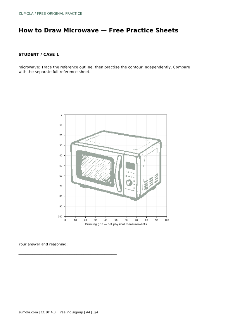
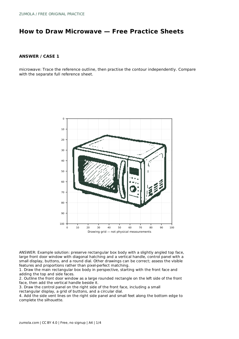
microwave: Trace the reference outline, then practise the contour independently. Compare with the separate full reference sheet.
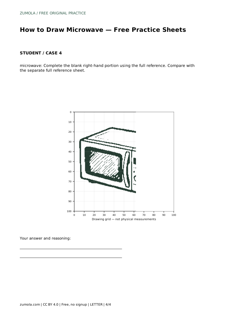
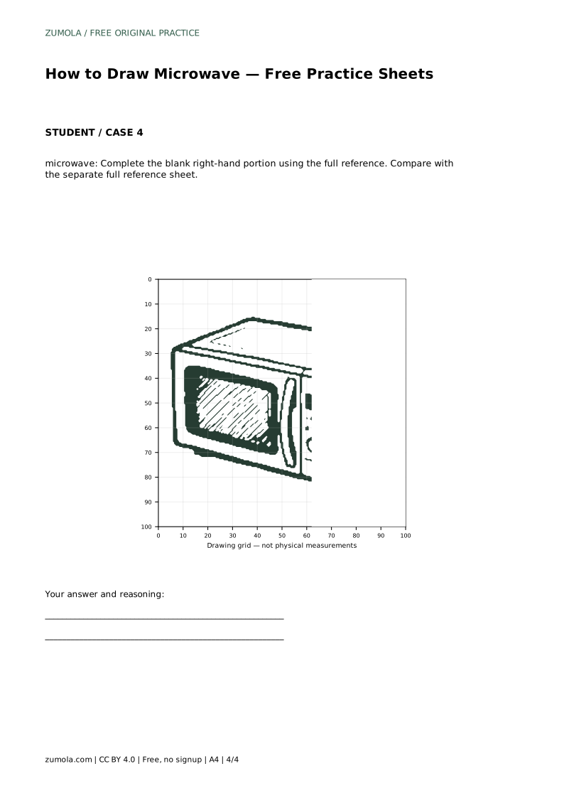
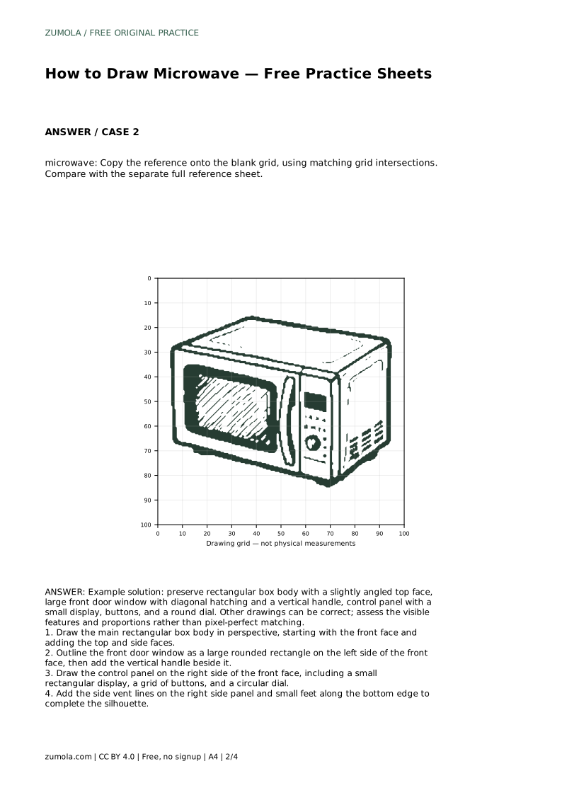
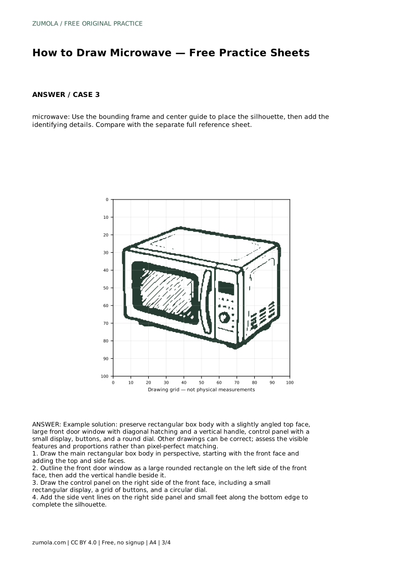
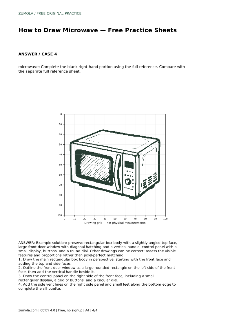
Example solution: preserve rectangular box body with a slightly angled top face, large front door window with diagonal hatching and a vertical handle, control panel with a small display, buttons, and a round dial. Other drawings can be correct; assess the visible features and proportions rather than pixel-perfect matching. Draw the main rectangular box body in perspective, starting with the front face and adding the top and side faces. Outline the front door window as a large rounded rectangle on the left side of the front face, then add the vertical handle beside it. Draw the control panel on the right side of the front face, including a small rectangular display, a grid of buttons, and a circular dial. Add the side vent lines on the right side panel and small feet along the bottom edge to complete the silhouette.
No. A simple angled top and side face is enough to suggest depth. Full perspective is optional and can make the drawing more complex than necessary.
There is no fixed number. A small grid of three to six buttons is enough to read as a control panel. Keep the buttons simple and aligned.
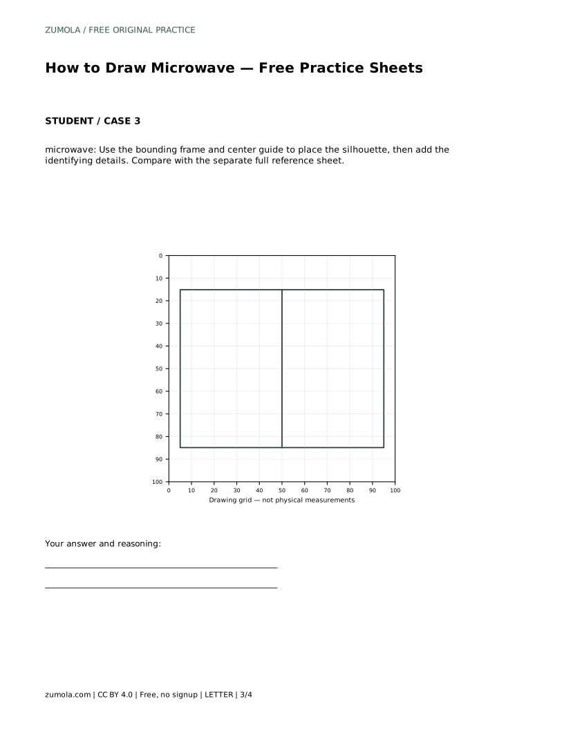
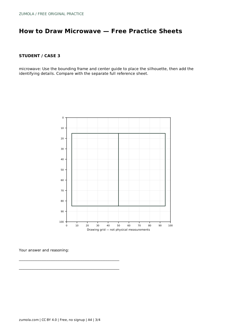
Yes. The grid and bounding-frame sheets are designed for copying and guided placement. Tracing is only one option; you can also draw independently and compare with the reference.
All drawing practice · Free coordinate paper
Original resources · CC BY 4.0 · Free for personal and classroom use with attribution.