Reference diagrams
LETTER · Download PDF
A4 · Download PDF
Free original resources
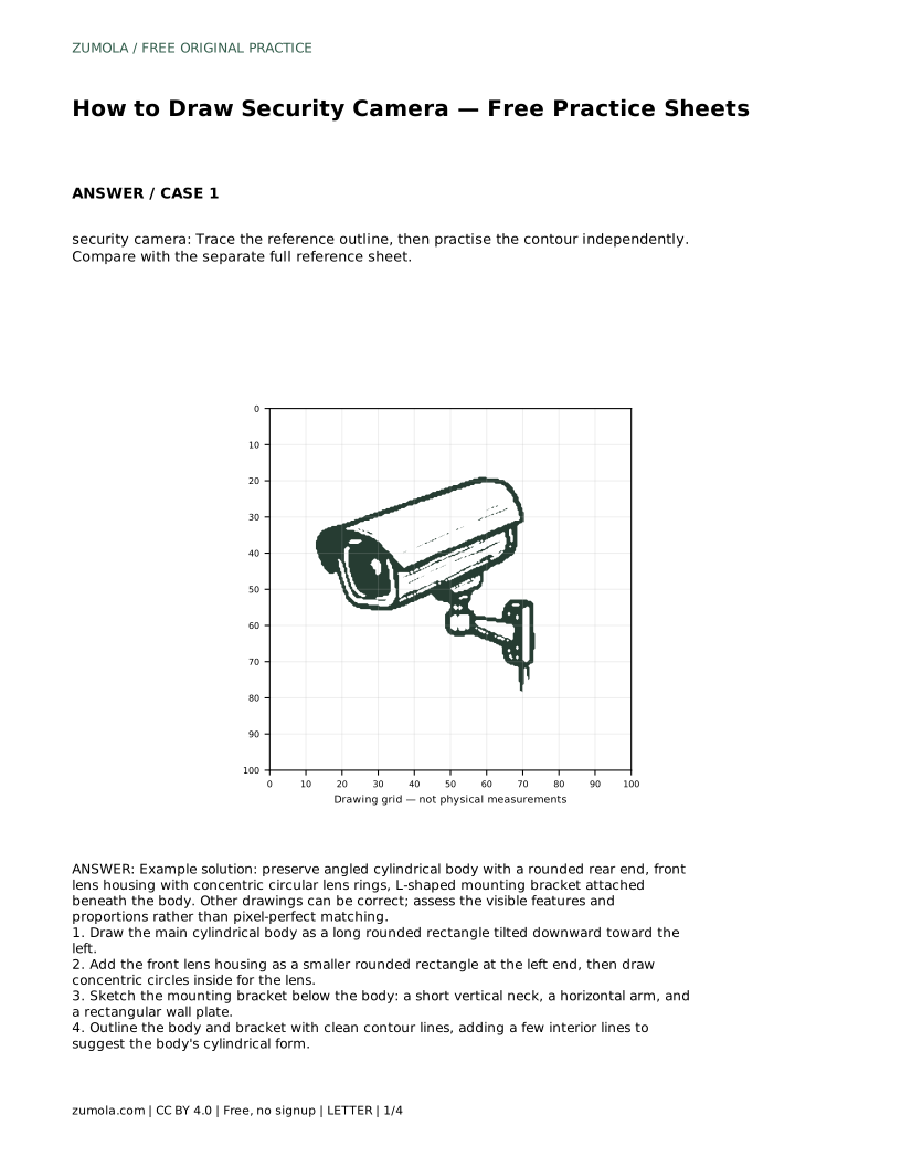
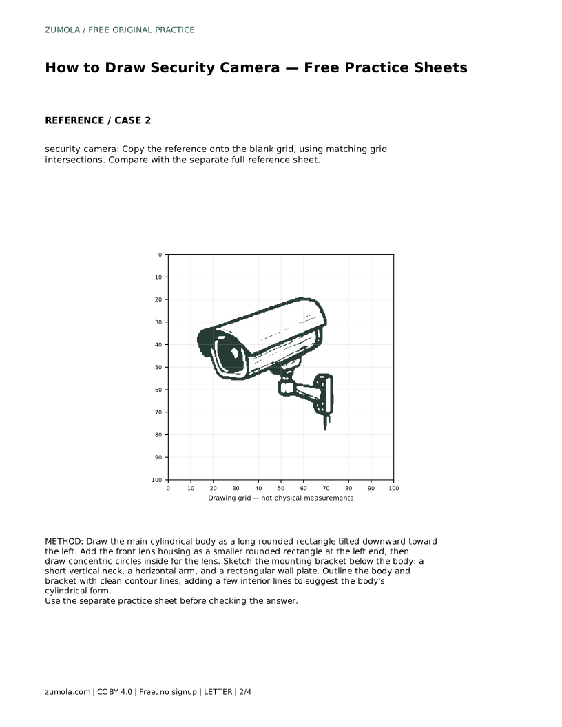
Learn to draw a security camera by building its tilted cylindrical body, concentric lens rings, and L-shaped mounting bracket, then checking proportions against a reference.
Four original cases, with reference diagrams, practice sheets and worked answers. Everything is free; no signup required.
LETTER · Download PDF
A4 · Download PDF
LETTER · Download PDF
A4 · Download PDF
LETTER · Download PDF
A4 · Download PDF
Use A4 or US Letter to match your printer. Use the stated values and conditions to solve each exercise; diagrams are not physical measuring rulers.
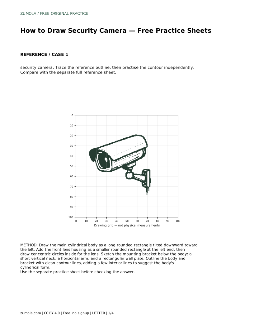
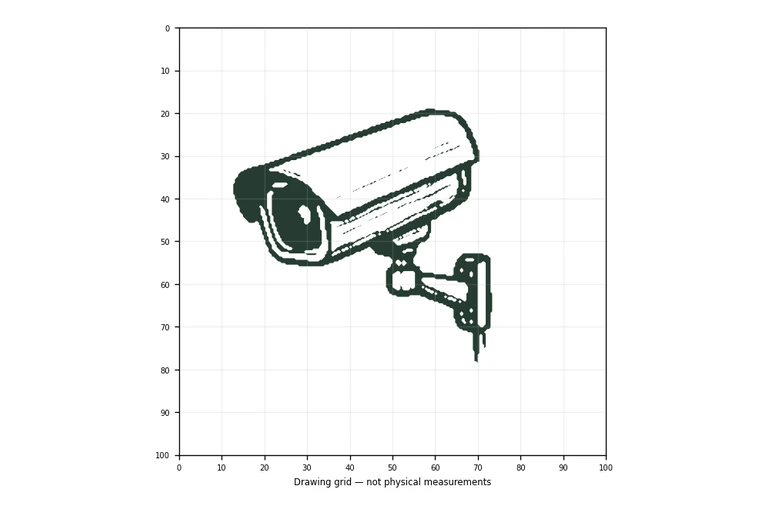
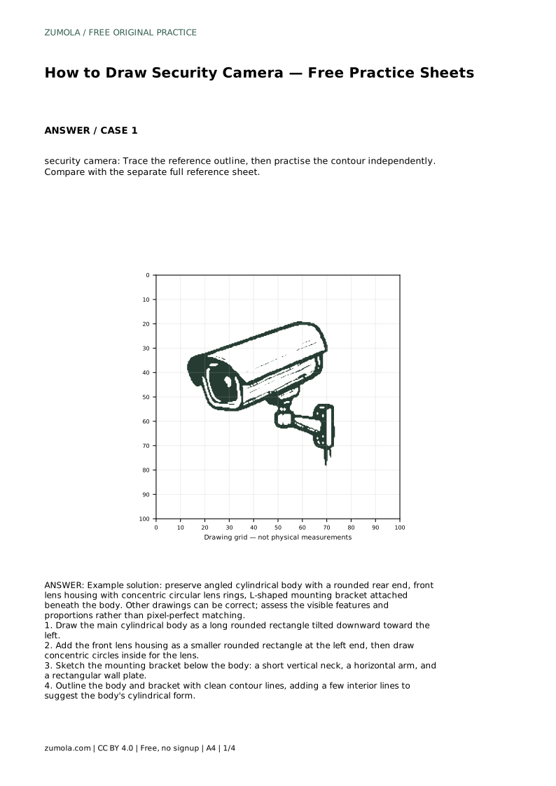
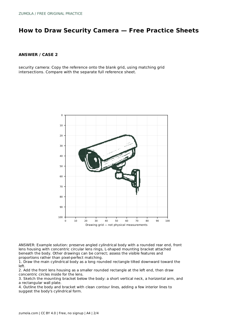
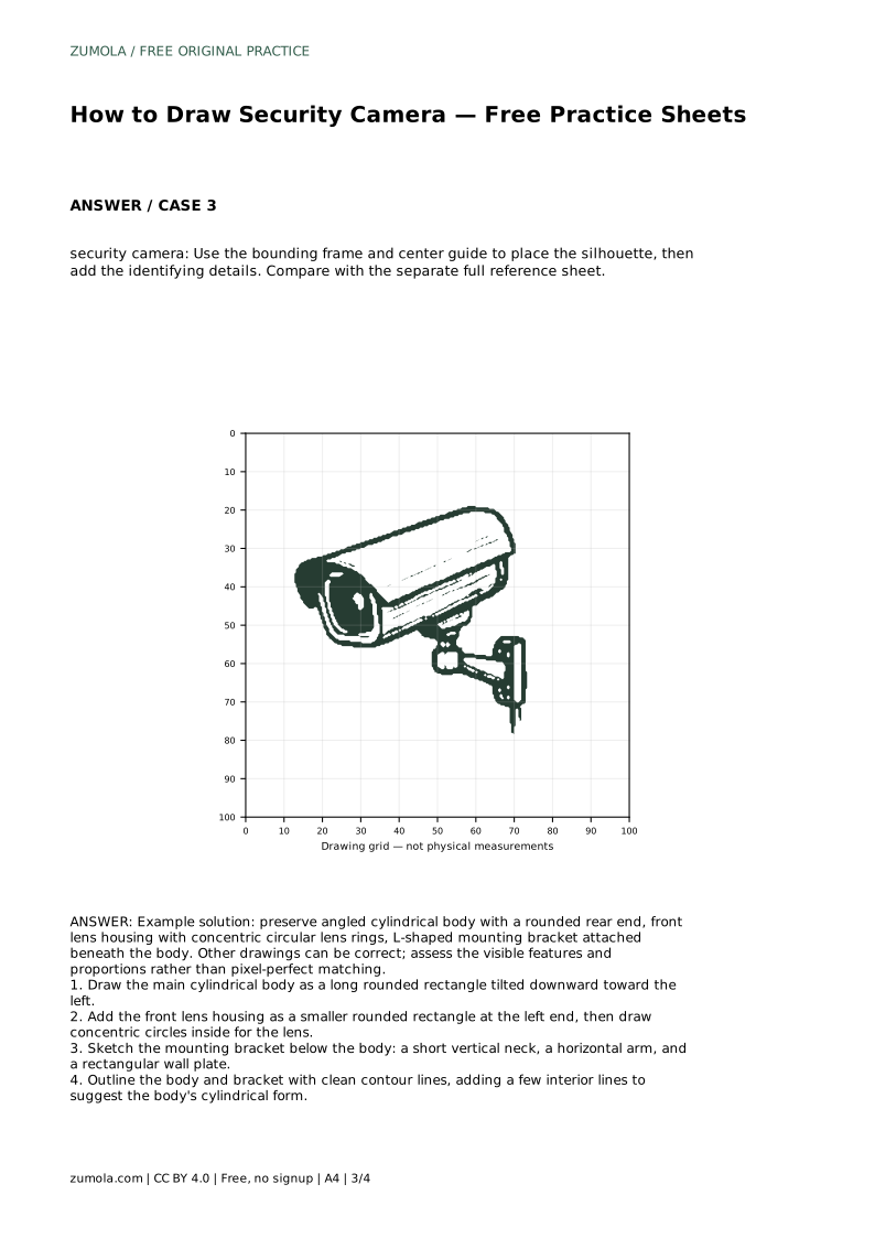
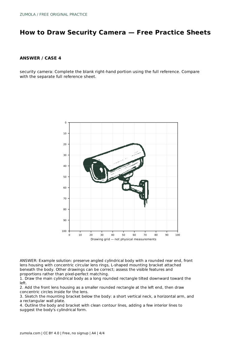
A security camera drawing is mostly a study in angled cylinders and clear attachments. The body leans downward, the lens housing sits at the front, and the bracket connects the camera to a wall plate. This page walks through that structure step by step, then explains how to compare your drawing with a separate reference sheet. Because drawings can be correct in more than one way, judge visible features and proportions rather than pixel-perfect matching.
Begin by placing the largest shape: the camera body. Treat it as a long rounded rectangle tilted downward toward the left. The tilt matters because it establishes the camera's viewing direction; if the body sits level, the drawing loses its sense of aiming at a subject below.
At the left end, add the front lens housing as a smaller rounded rectangle. Inside it, draw concentric circles for the lens rings. Keep the circles centered on the housing so the lens reads as a single front-facing unit rather than a set of unrelated loops. A few interior lines along the body can suggest its cylindrical form without turning the drawing into a technical diagram.
The bracket is what makes the object read as a mounted camera rather than a floating tube. Build it from three connected parts: a short vertical neck beneath the body, a horizontal arm, and a rectangular wall plate. Check that the neck meets the underside of the body and that the arm reaches the plate without gaps or overlaps.
Proportions do the rest. The wall plate should be large enough to look like a mounting surface but not so large that it dominates the camera. The arm should be long enough to separate the body from the wall. When the bracket is complete, trace over the main outlines with clean contour lines, keeping the lens circles lighter than the outer silhouette.
Once your drawing is complete, set it beside the separate full reference sheet. Compare the angle of the body, the position of the lens housing, the spacing of the concentric rings, and the shape of the bracket. Ask whether the camera still appears to point downward and whether the bracket visibly supports it.
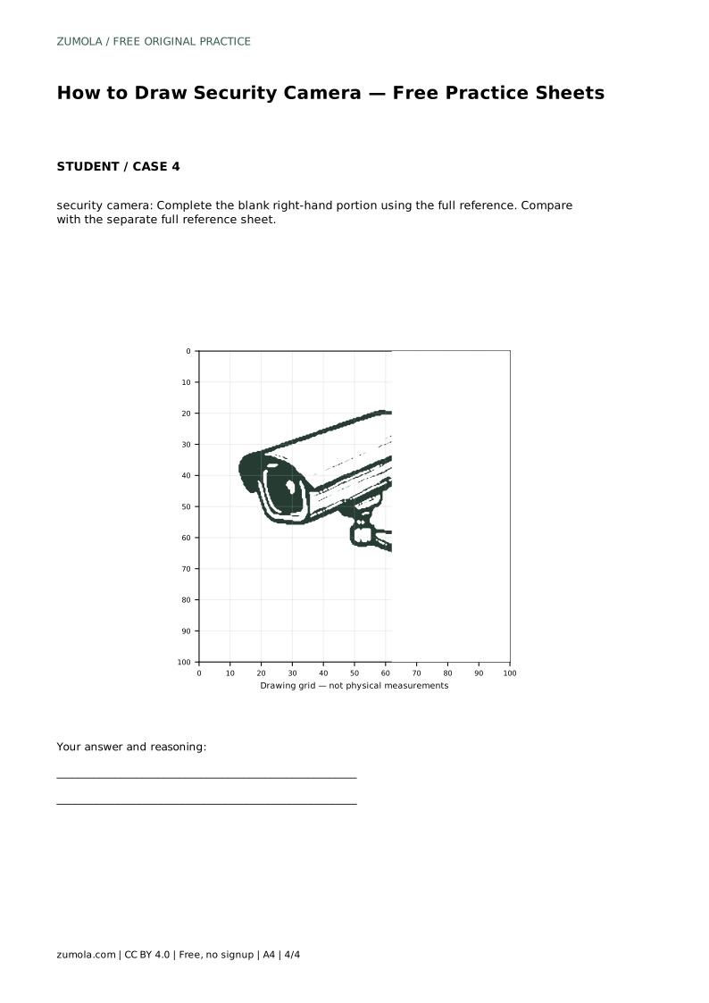
Different drawings can be correct. A slightly longer body or a wider wall plate may still preserve every identifying feature. Use the comparison to catch missing parts or distorted proportions, not to force an exact copy. If you used a grid, tracing outline, bounding frame, or partial-reference version, the same feature checklist applies.
After one complete drawing, try the same camera at a different scale or with the body tilted more steeply. Keep the lens rings concentric and the bracket attached beneath the body. Practising variations helps you understand the structure instead of memorizing one outline.
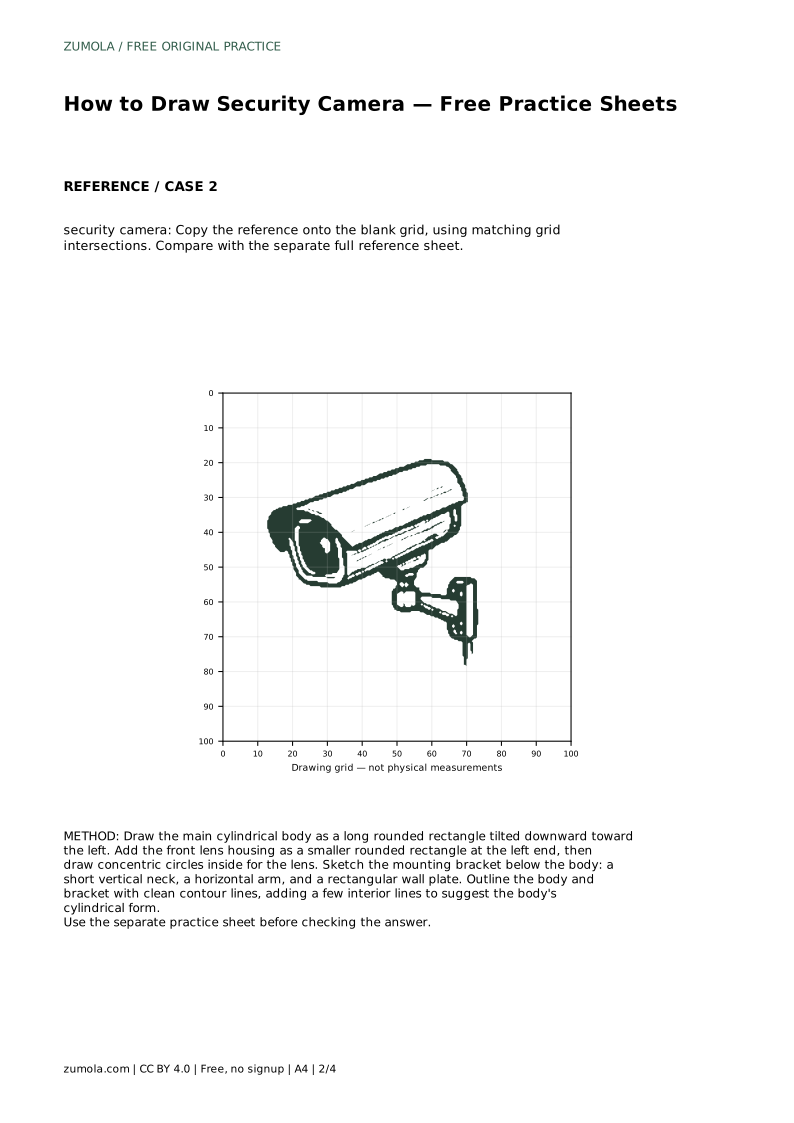
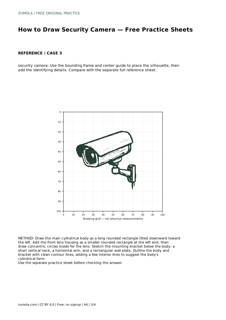
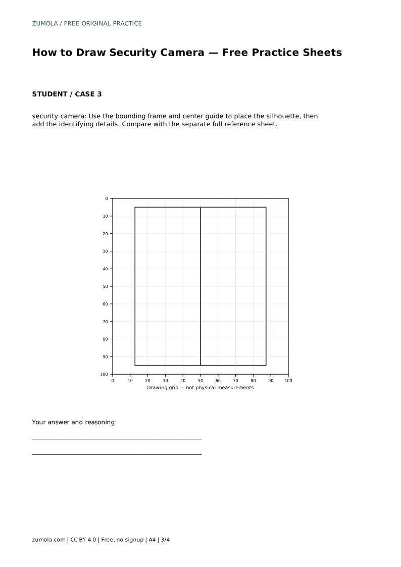
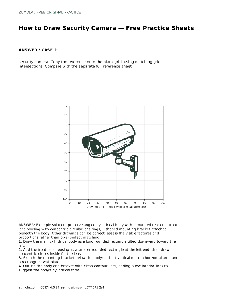
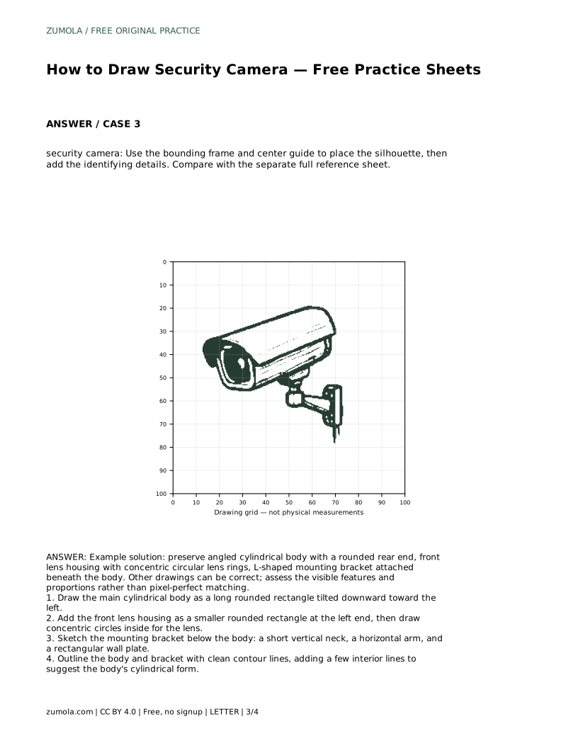
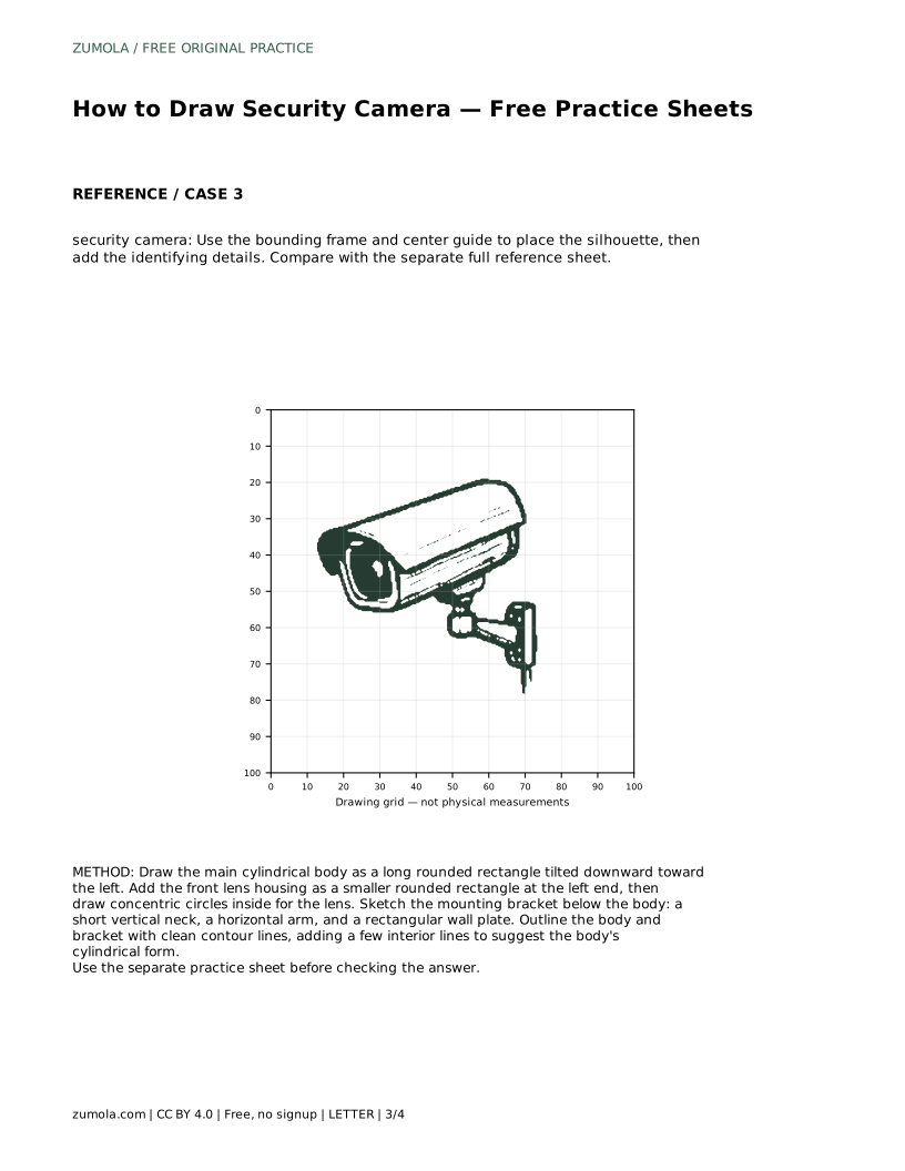
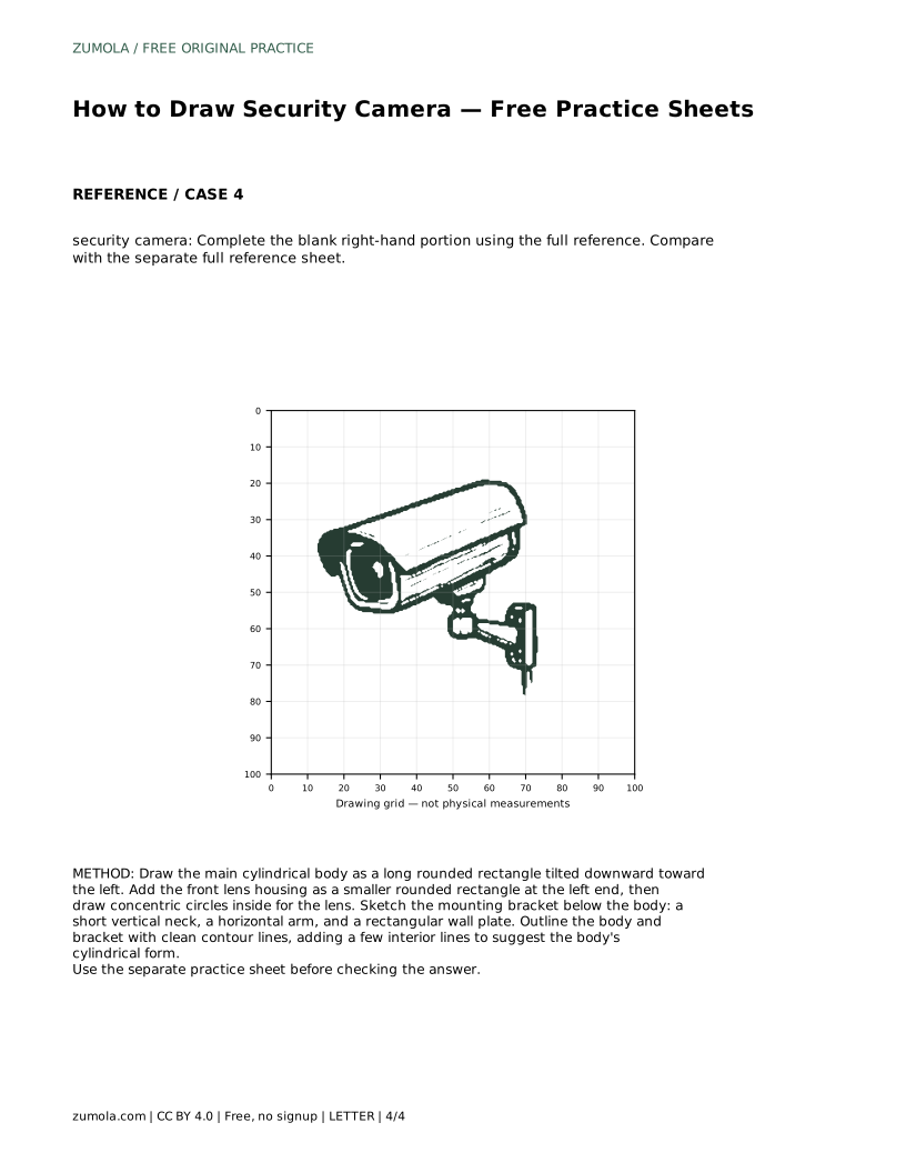
If you use a grid version, match intersections for the body and bracket before adding the lens circles. If you use a bounding frame and center guide, place the silhouette first, then add the identifying details. Each practice format targets the same set of visible features.
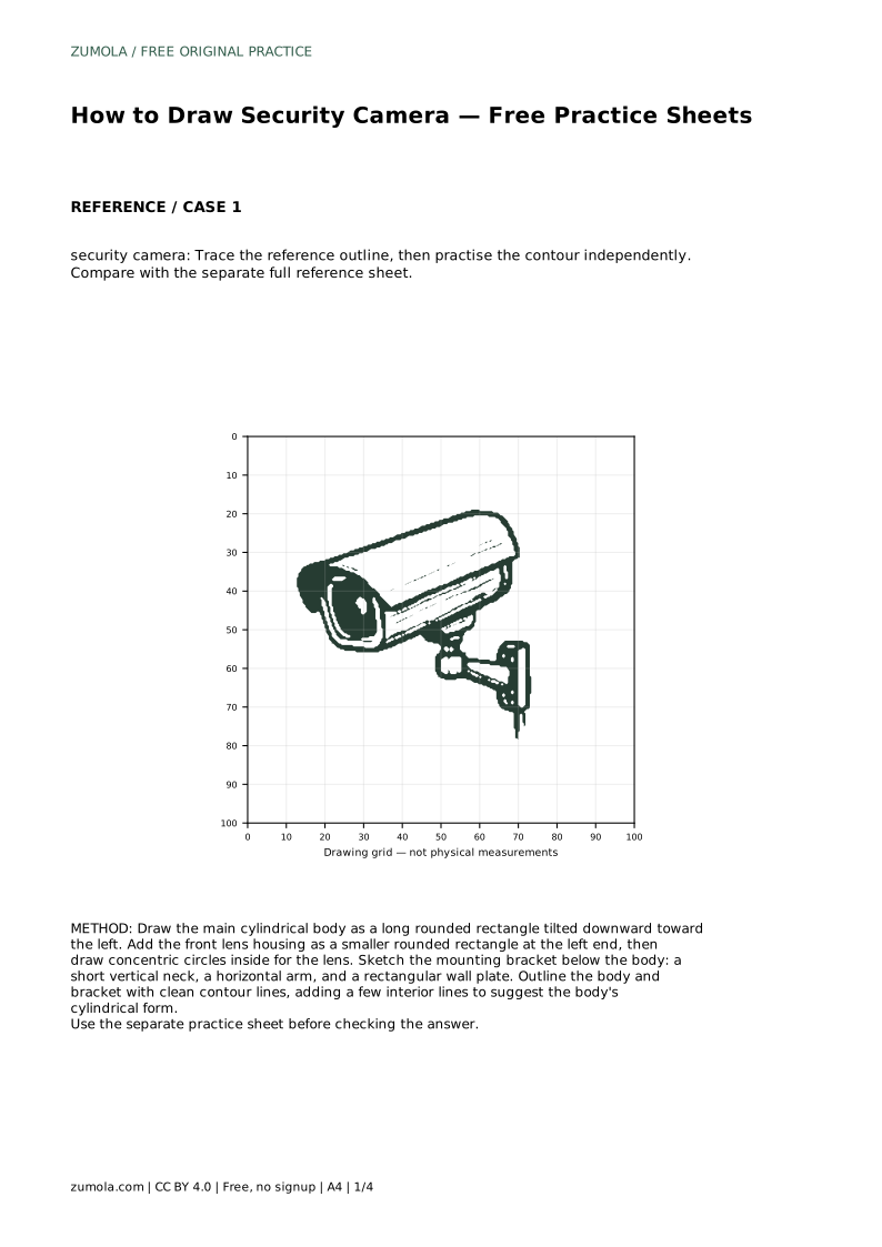
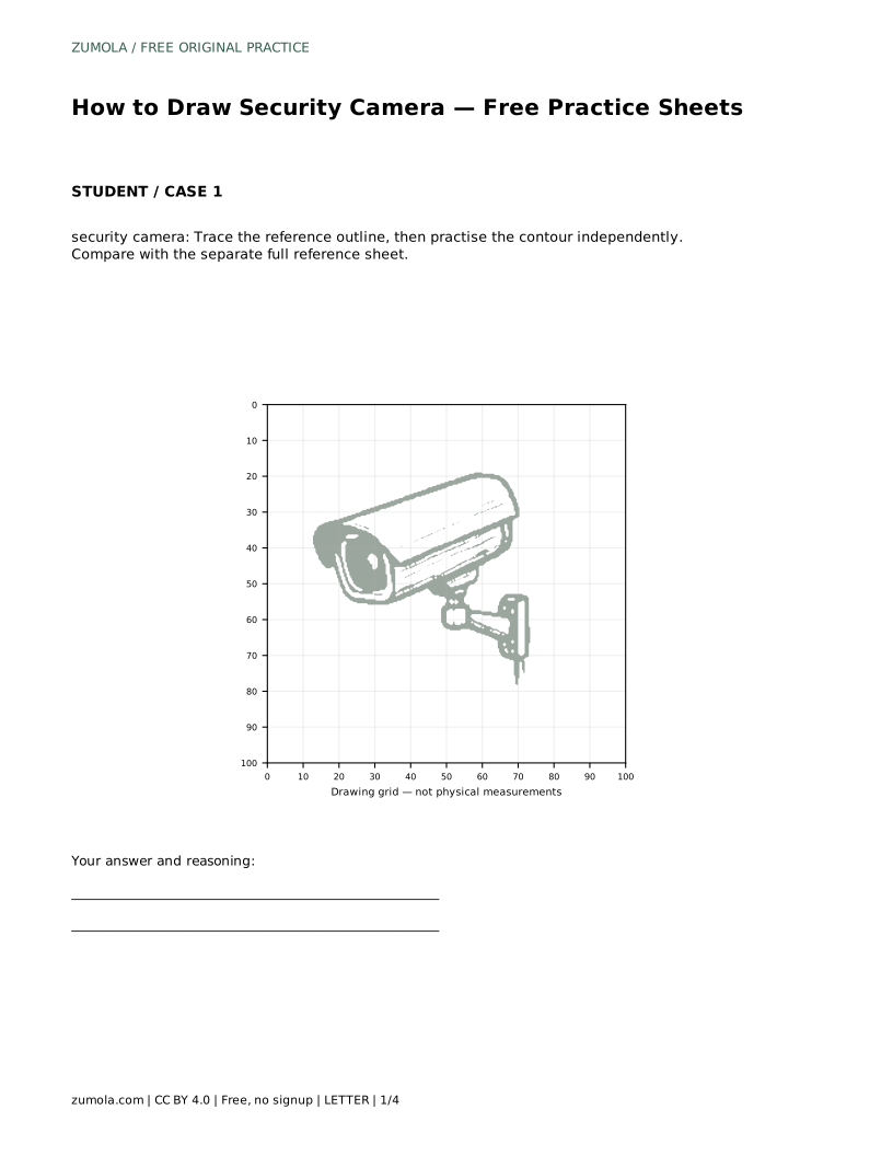
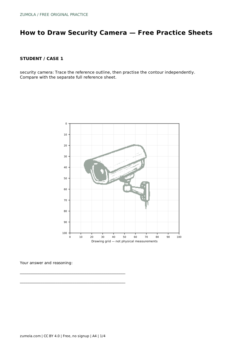
security camera: Trace the reference outline, then practise the contour independently. Compare with the separate full reference sheet.
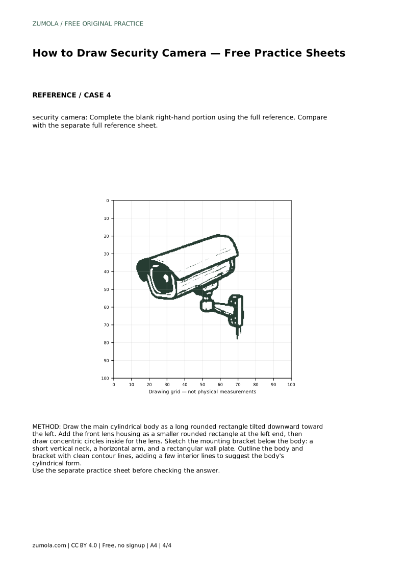
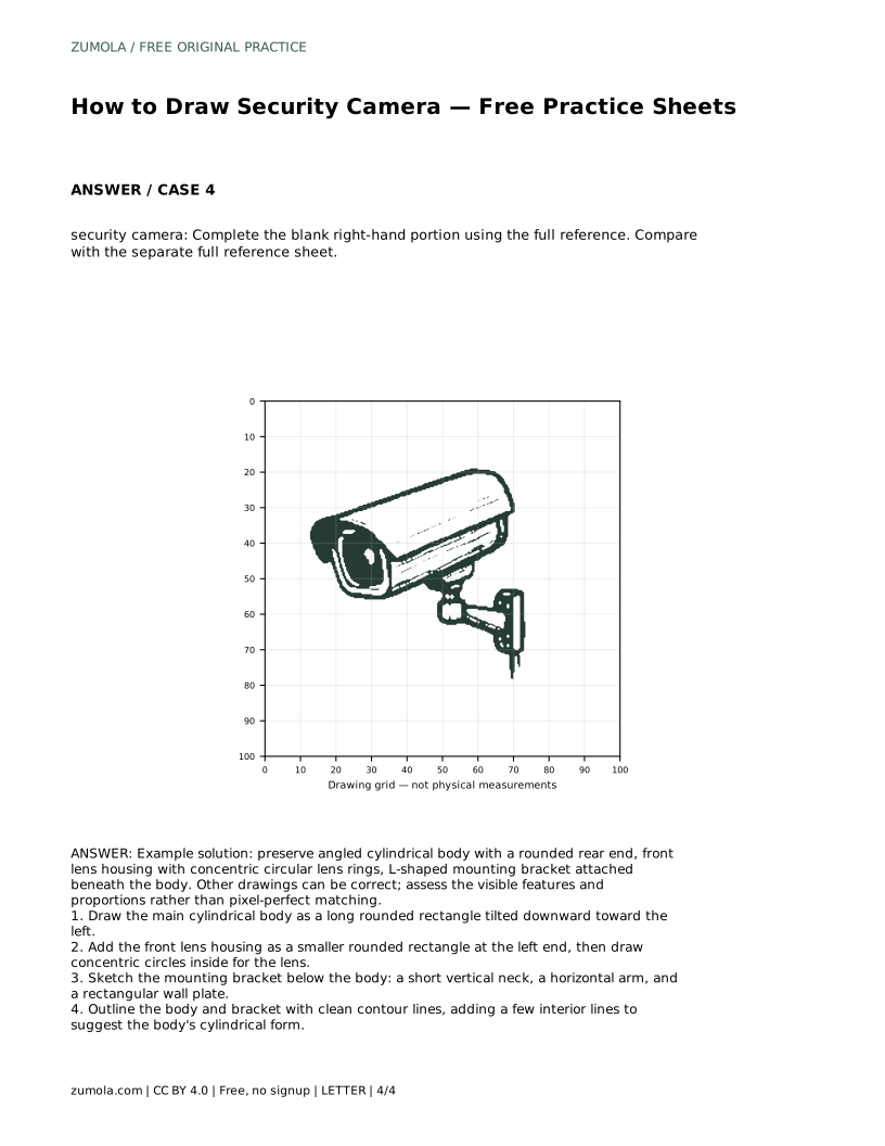
Example solution: preserve angled cylindrical body with a rounded rear end, front lens housing with concentric circular lens rings, L-shaped mounting bracket attached beneath the body. Other drawings can be correct; assess the visible features and proportions rather than pixel-perfect matching. Draw the main cylindrical body as a long rounded rectangle tilted downward toward the left. Add the front lens housing as a smaller rounded rectangle at the left end, then draw concentric circles inside for the lens. Sketch the mounting bracket below the body: a short vertical neck, a horizontal arm, and a rectangular wall plate. Outline the body and bracket with clean contour lines, adding a few interior lines to suggest the body's cylindrical form.
The reference shows a downward tilt, which communicates the camera's viewing direction. A different angle can still be correct if the body, lens housing, and bracket remain clearly related.
Use the reference sheet as your guide. The important point is that the rings are concentric and centered inside the front lens housing.
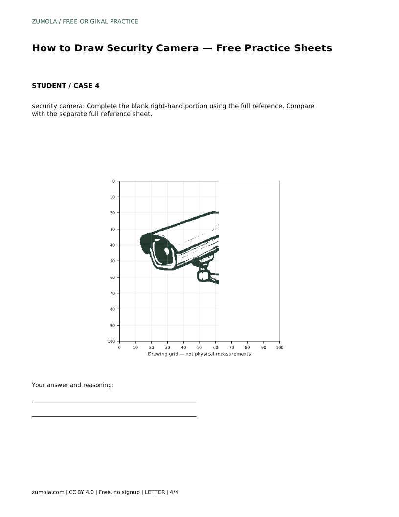
Yes. Match grid intersections or complete the missing portion, then compare the finished drawing with the separate full reference sheet using the same feature checklist.
All drawing practice · Free coordinate paper
Original resources · CC BY 4.0 · Free for personal and classroom use with attribution.