Free original resources
Section View Drawing Exercises: Cutting Planes and Hatching Explained
Learn how a cutting plane creates a section view, how to keep orthographic views consistent, and how to apply hatching correctly with a worked example and rubric.
Free resources
Letter & A4
PDF & SVG
Letter & A4
PDF & SVG
Make it yours.
Free · no signup · calculated in your browser
Your free printable kit.
Original reference, student practice and separate worked answers. No account or payment.
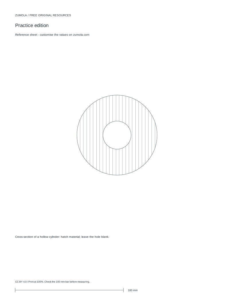
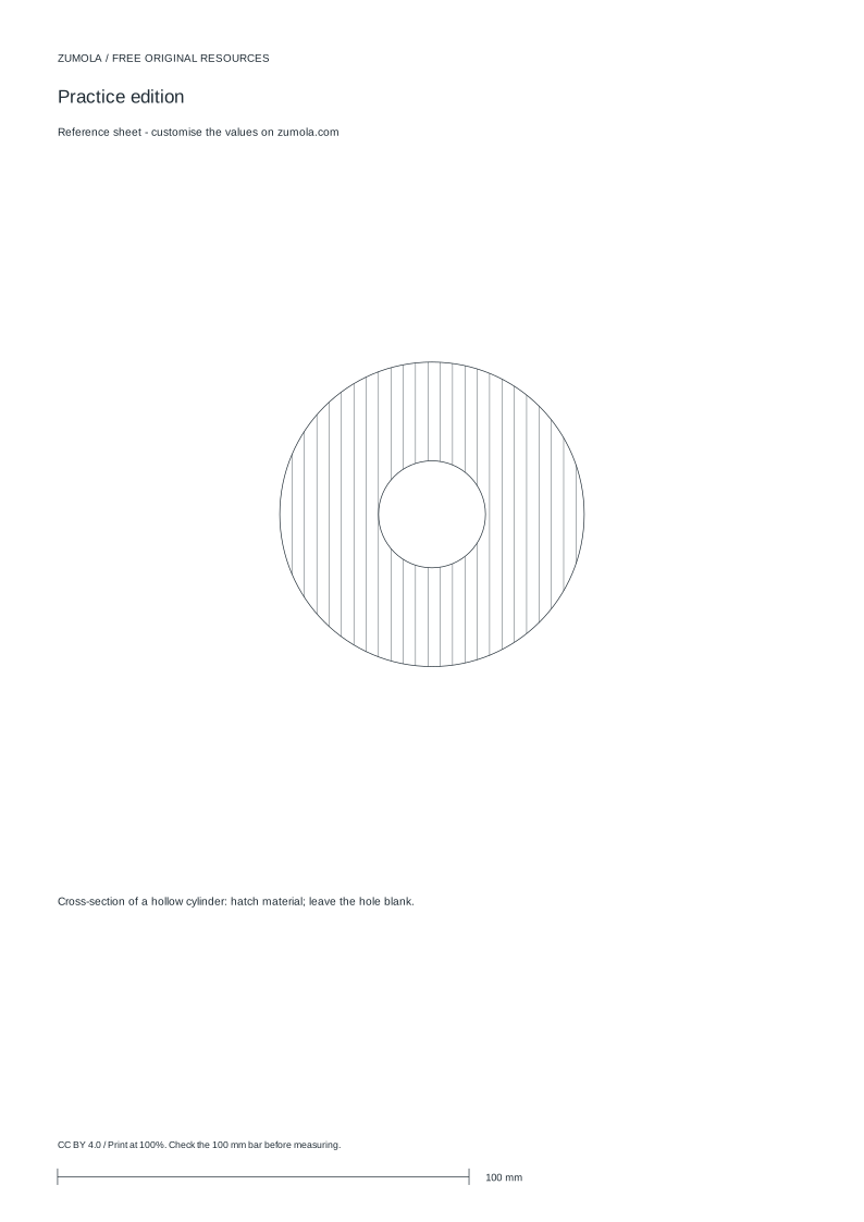
Practice worksheet
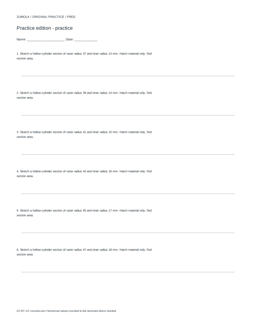
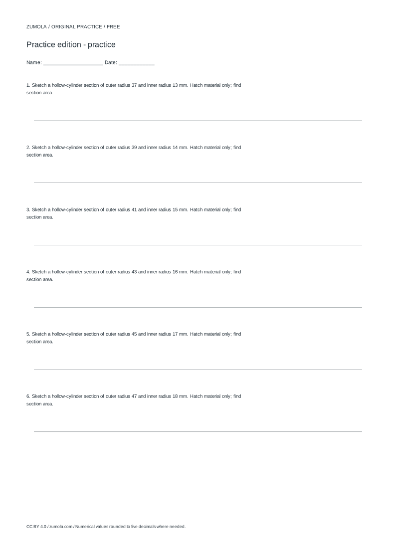
Worked answers / rubric
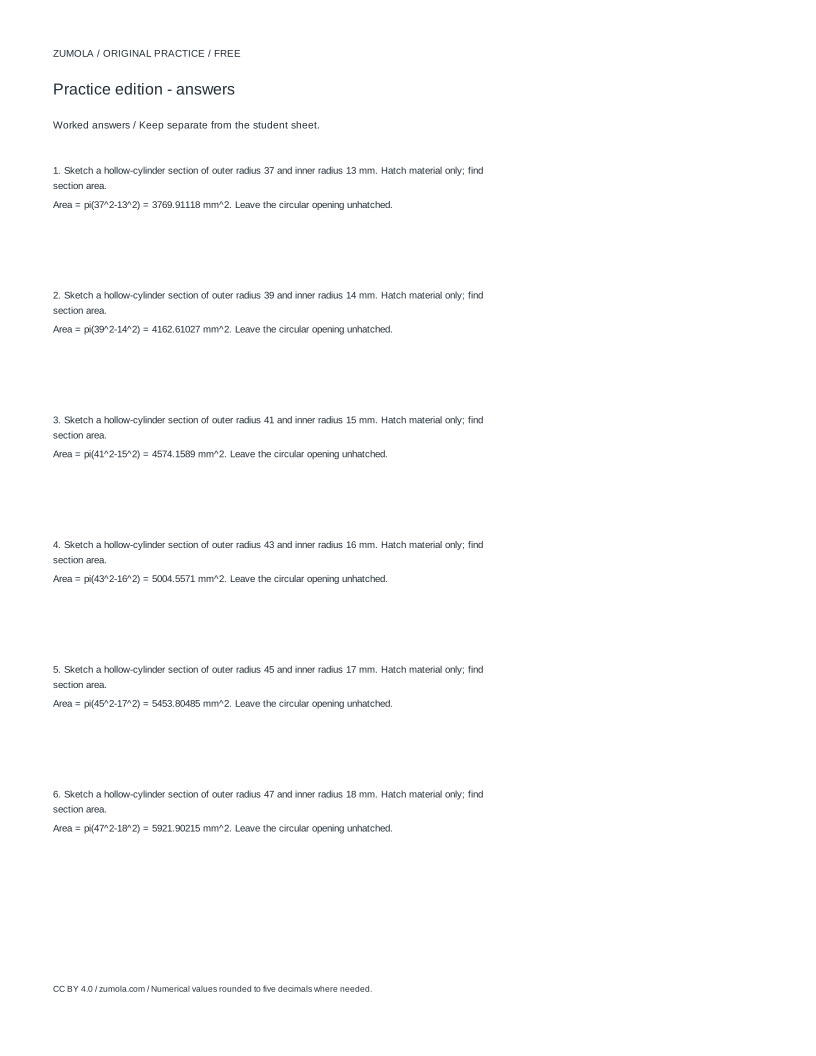
Print at Actual size / 100%. Check the calibration bar before using physical dimensions.
A section view shows what a solid looks like when an imaginary cutting plane slices through it, revealing interior form that hidden lines only hint at. These exercises focus on one skill: using a cutting plane to explain the section shape and the hatching on a simple solid. You will set an observation direction, keep front, top, and side views geometrically consistent, and state units in millimetres unless noted. The goal is accurate conceptual reasoning, not manufacturing or construction specification.
What a cutting plane does
A cutting plane is an imaginary flat surface passed through the object. The part of the object between the viewer and the plane is removed, and the exposed cut face is drawn as the section. The outline of that cut face is the section shape; the surrounding visible edges remain as normal outlines. A section view is therefore not a different object, but the same object viewed after a defined cut.
State the observation direction explicitly, for example viewing from the front after a vertical cut. Use first-angle or third-angle projection consistently and label it. Keep units in millimetres unless stated. The front, top, and side views must agree: a feature that appears at a given height in the front view must appear at the same height in the side view, and widths must match between front and top views.
- Choose the cutting plane position and orientation, such as vertical through the centre.
- Mark the viewing direction with arrows perpendicular to the cut.
- Draw the cut face outline first, then add visible edges behind the plane.
- Check that all orthographic views share the same dimensions and feature positions.
Hatching the cut face
Hatching is a set of thin, evenly spaced parallel lines drawn only on the cut face. It signals which surfaces were sliced by the plane, not which surfaces are merely visible. Use one consistent angle and spacing within a single part. If two separate parts are cut, vary the angle or spacing between them so the parts remain distinguishable.
Do not hatch hidden edges, background surfaces, or holes that the plane passes through without cutting material. A circular hole cut through its axis produces an open gap in the hatched region, not a hatched circle. Keep hatch lines clear of dimension text and outlines so the section shape stays readable.
- Identify every region of material intersected by the cutting plane.
- Apply parallel hatch lines at a consistent angle and spacing.
- Leave voids and holes unhatched where the plane passes through empty space.
- Confirm hatch boundaries match the cut face outline exactly.
Worked reasoning for a hollow cylinder
Consider a hollow cylinder with outer diameter 37 mm and inner diameter 13 mm, cut by a plane containing its axis. The section shape is two rectangles separated by a central gap. The outer width is 37 mm and the inner gap width is 13 mm, so each solid wall is (37 − 13) ÷ 2 = 12 mm wide. The height equals the cylinder length, which must be stated in the exercise.
The cut area can be checked as the outer rectangle minus the inner rectangle: 37 × L − 13 × L = 24L square millimetres, where L is the length. For the schematic values recorded for this exercise, the section area is about 3769.91 square millimetres, which corresponds to L ≈ 157.08 mm. Treat that number as a consistency check, not a manufacturing dimension. Hatch only the two wall rectangles, leaving the central gap clear.
- Draw the outer rectangle 37 mm wide and the stated length tall.
- Draw the inner gap 13 mm wide, centred, and remove it from the hatched region.
- Hatch the two remaining wall rectangles with matching angle and spacing.
- Verify wall width: (37 − 13) ÷ 2 = 12 mm on each side.
Try this example
A hollow cylinder has outer diameter 37 mm, inner diameter 13 mm, and length 40 mm. A cutting plane contains the axis. Describe the section shape, wall width, and hatching.
Show the worked explanation
The section is two rectangles separated by a central gap. Outer width is 37 mm, inner gap width is 13 mm, and each wall is (37 − 13) ÷ 2 = 12 mm wide. Height is 40 mm. Hatch only the two wall rectangles, leaving the 13 mm gap unhatched. The cut area is 37 × 40 − 13 × 40 = 960 square millimetres.
Common mistakes
- Hatching the entire outline, including holes and gaps. Hatch only material cut by the plane; leave holes and voids unhatched and check that hatch boundaries follow the cut face.
- Drawing a section view that does not align with the front, top, or side views. Compare shared dimensions and feature heights across all views before finalising the section; correct any mismatch in position or size.
- Omitting the cutting plane direction or projection convention. Label the viewing direction with arrows and state first-angle or third-angle projection, plus units in millimetres unless noted.
Check your work
- Cutting plane position and viewing direction are clearly stated.
- Projection convention and units in millimetres are labelled.
- Front, top, and side views agree on shared dimensions and feature positions.
- Hatching appears only on material cut by the plane, with consistent angle and spacing.
- Holes and voids remain unhatched and hatch boundaries match the cut face.
- Section shape is described accurately without claiming manufacturing specification.
Questions before you start
Is a section view the same as a hidden-line view?
No. Hidden lines suggest interior edges with dashed lines, while a section view removes material in front of the cutting plane and shows the exposed cut face with hatching.
Should hatch lines cross dimension text?
No. Keep hatch lines clear of dimension text and outlines so the section shape and measurements remain readable.
Can I use these exercises as manufacturing drawings?
No. These are teaching examples for section-view reasoning only; they are not manufacturing or construction specifications.