Free printable resources · Original practice
Dot grid paper.
A lighter framework.
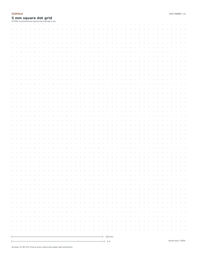
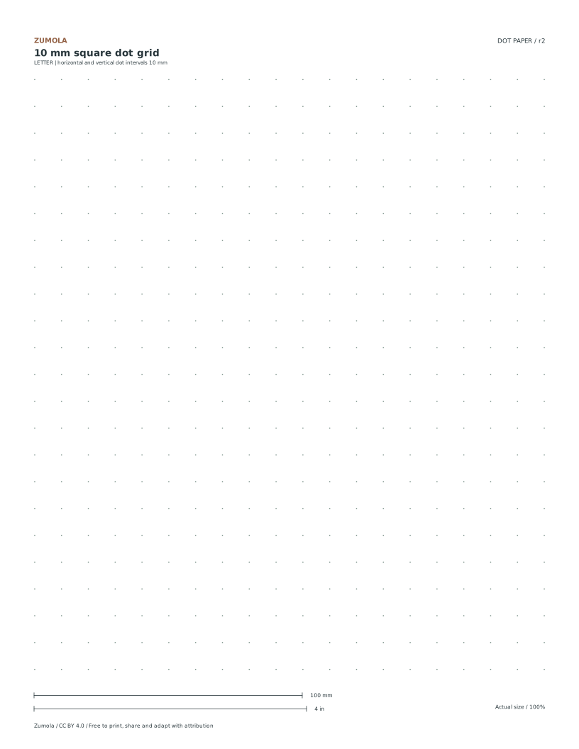
Choose 5 mm or 10 mm square dots. Keep the structure of a grid without full lines, then compare the same original outline at two sizes.
Square dot arrangement.
5 mm & 10 mm intervals.
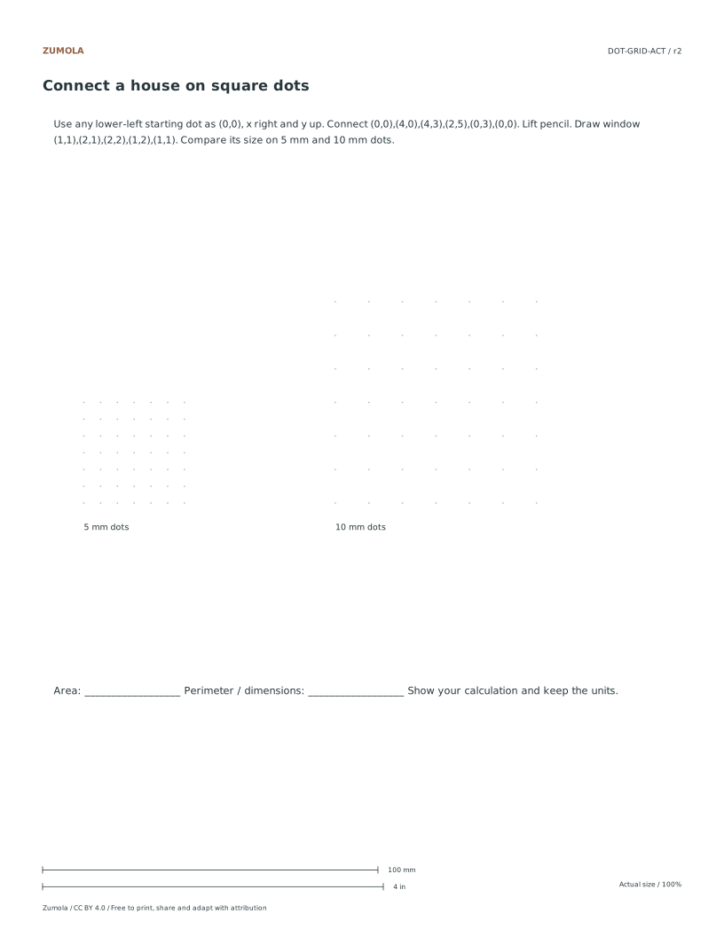
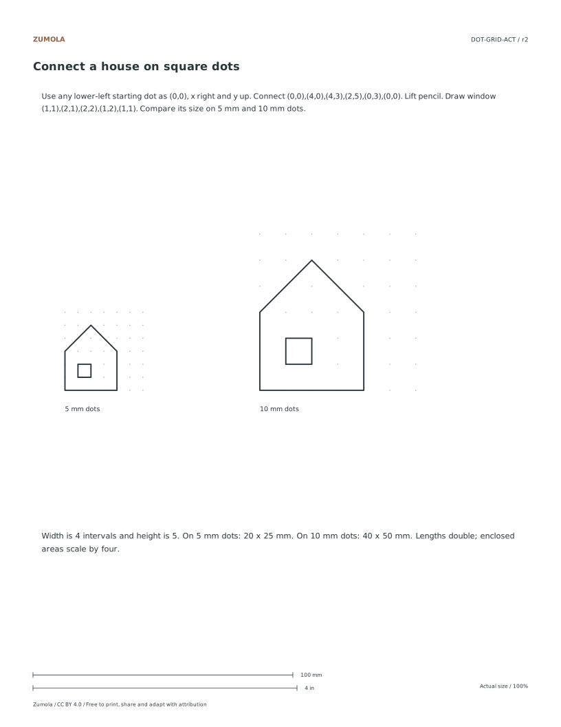
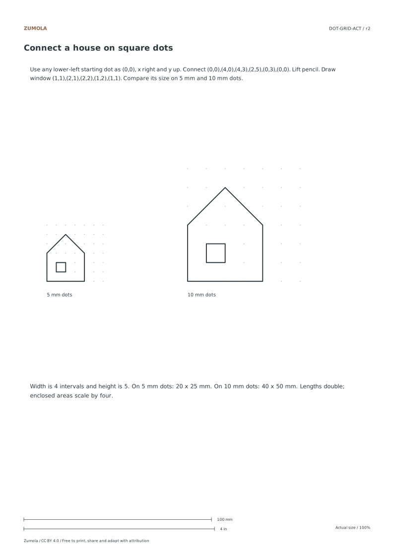
Two-size drawing exercise.
More ways to practice
Count intervals, not dots
A dot grid is a set of points at fixed spacing. When you plan a shape, describe each edge by the number of intervals it crosses, not by the number of dots it touches. A segment spanning four intervals covers four spacings; counting five dots along the same line describes the same length but invites off-by-one errors when you repeat it.
Keep the unit explicit. At 5 mm spacing, four intervals equal 20 mm. At 10 mm spacing, the same four intervals equal 40 mm. The interval count stays constant while the physical length doubles, which is exactly what makes the grid useful for comparing the same structure at two sizes.
- Mark a starting dot and label it A.
- Draw a horizontal edge across four intervals and label the end B.
- From B, draw a vertical edge across three intervals to C.
- Close the shape back to A with a diagonal, then count the intervals it crosses to check it matches your plan.
- Repeat the same interval counts at the other spacing and compare the two outlines side by side.
Alignment drift and how to catch it
Drift appears when a line that should pass through several dots misses one by a small amount. On a dot grid this is easy to see because the dots act as checkpoints. If your edge crosses a dot near its start but sits between dots near its end, the line has rotated slightly rather than stayed parallel to the grid.
Check alignment before adding detail. A short edge hides drift; a long edge exposes it. Draw the longest straight edge first and confirm it passes through each intermediate dot, then build the shorter edges from its endpoints.
- Draw the longest edge first and inspect every dot it should cross.
- If a dot is missed, erase and redraw from the two endpoints rather than nudging the middle.
- Check that corners land on dots, not between them.
- Confirm the closing edge returns to the starting dot exactly.
A practical variation: same shape, two spacings
Use the interval method to test proportion control. Build one shape at 5 mm spacing, then rebuild it at 10 mm spacing using identical interval counts. The two outlines should be similar in shape, with every length doubled. If one edge looks proportionally longer at the larger spacing, an interval was miscounted.
This variation also trains you to separate structure from scale. Composition decisions such as where a shape sits relative to the sheet edge should be made in intervals so they transfer between sizes. Physical margins, by contrast, stay fixed in millimetres and must be checked separately.
- Record the interval count for each edge before drawing.
- Draw the 5 mm version and note where each corner sits.
- Draw the 10 mm version using the same counts.
- Compare edge ratios, not absolute lengths.
- Note any edge whose ratio changed and recount its intervals.
Try this example
Plan a right-angled L shape on a dot grid: a horizontal edge of four intervals, then a vertical edge of three intervals downward from its right end. Repeat at 5 mm and 10 mm spacing.
Show the worked explanation
At 5 mm spacing the horizontal edge is 4 x 5 = 20 mm and the vertical edge is 3 x 5 = 15 mm. At 10 mm spacing the same interval counts give 40 mm and 30 mm. Both versions keep a 4:3 ratio between the two edges, so the shapes are similar and every length has doubled. If the 10 mm version shows a different ratio, one edge was miscounted; recount intervals from the corner dot.
Common mistakes
- Counting dots instead of intervals, so a four-interval edge is drawn as five dots wide. State each edge as a number of intervals and mark endpoints only; count gaps, not points.
- Correcting drift by bending the middle of a line. Erase the whole edge and redraw between the two endpoint dots so the line stays straight.
- Assuming fixed margins scale with the grid spacing. Treat margins as physical millimetres and check them independently of interval counts.
Check your work
- Every edge is described by an interval count before drawing.
- Longest edge is drawn first and passes through each intermediate dot.
- Corners land on dots rather than between them.
- The same interval counts are reused at both spacings.
- Edge ratios are compared rather than absolute lengths.
- Drift is corrected by redrawing the full edge, not bending its middle.
Questions before you start
Why describe edges in intervals rather than millimetres?
Intervals transfer directly between 5 mm and 10 mm sheets, so the same plan works at both sizes while physical lengths change predictably.
How do I know a line is aligned to the grid?
A correctly aligned edge passes through every intermediate dot along its path; a drifting edge starts on dots and ends between them.
Should I draw long or short edges first?
Draw the longest edge first, because it reveals drift that short edges hide, then build the remaining edges from its endpoints.