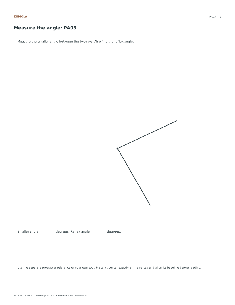
180° + 360° templates. 3 exercises + worked answers.
A reference, a task and a way to check it
Align the center and baseline, then follow the scale beginning at zero on your starting ray. Practice acute, obtuse and reflex angle checks.
Choose US Letter or A4 for prepared downloads. Original PDF and SVG files, worksheets and reference answers are free without signup. Collection packs contain the same individual pages in order.
Choose your paper and download
Download paper size
Every worksheet and answer is free. No signup.
Free original resource
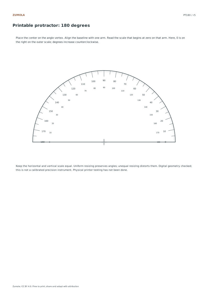
half-180 protractor reference
Original task with a separate reference answer. Letter or A4.
Use the student pack first, then compare the reference or answer. Packs are PDFs; individual sheets below also include editable SVG files. The paper choice applies to every download.
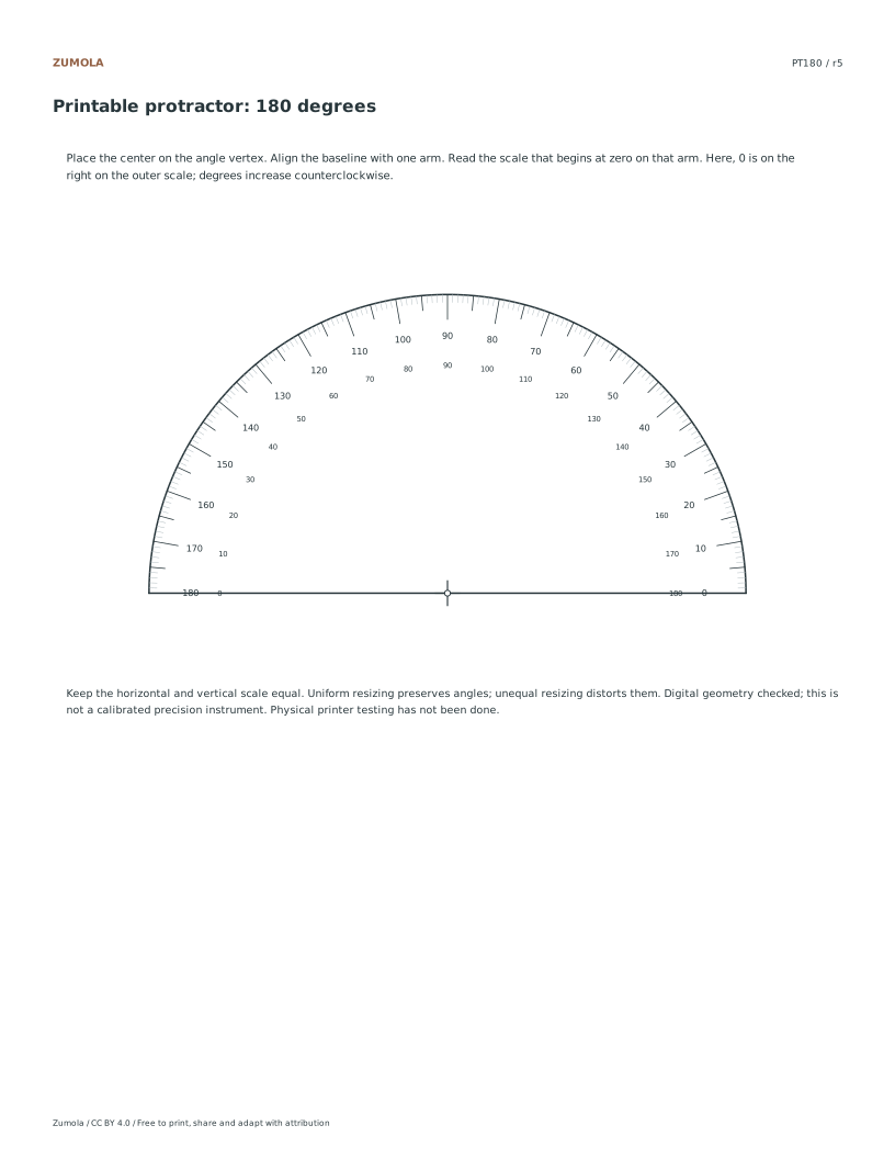
The 180° file has 1° ticks, longer 5° and 10° marks, and two opposing label rows. On our template the outer row begins at 0° on the right. Other protractors can label their rows differently, so use the row that starts at zero on your chosen ray instead of memorizing a universal inner-versus-outer rule.
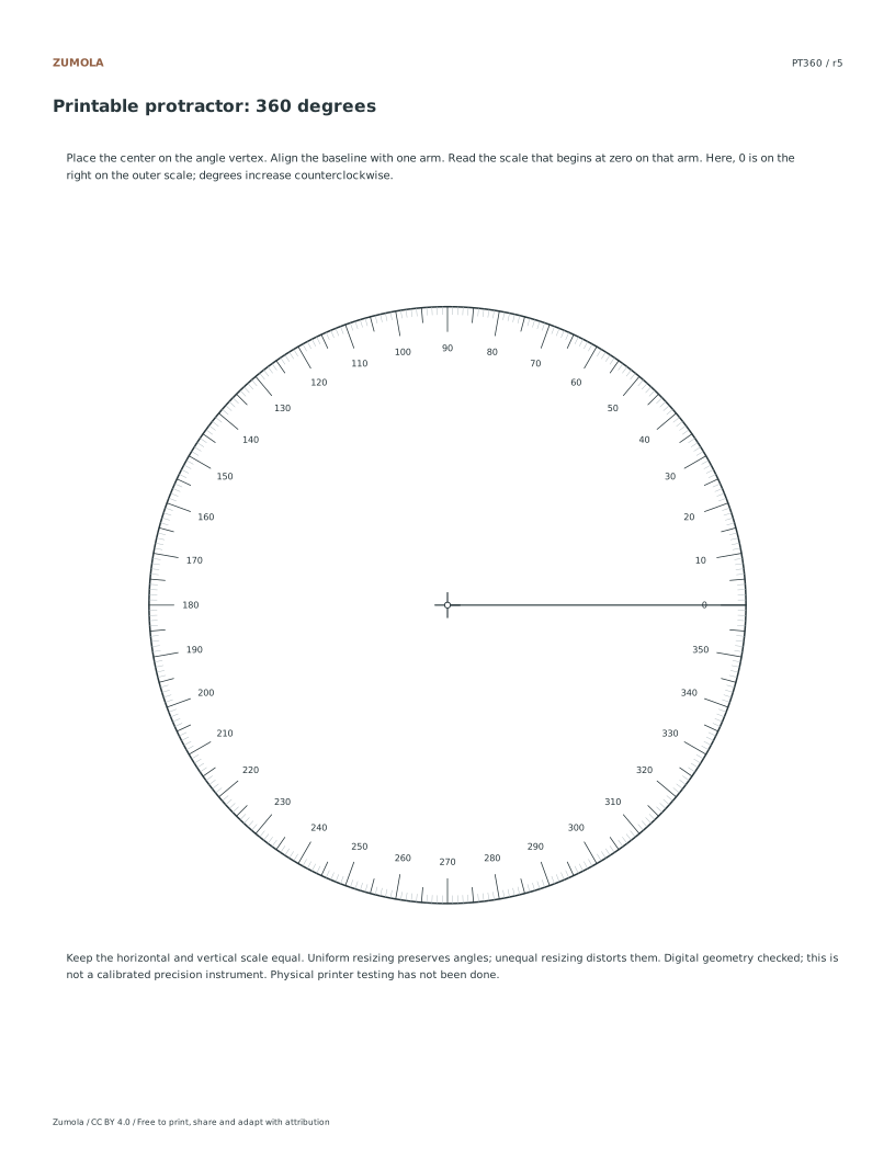
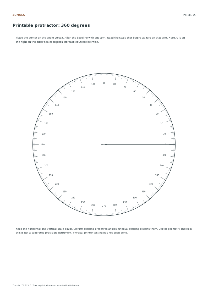
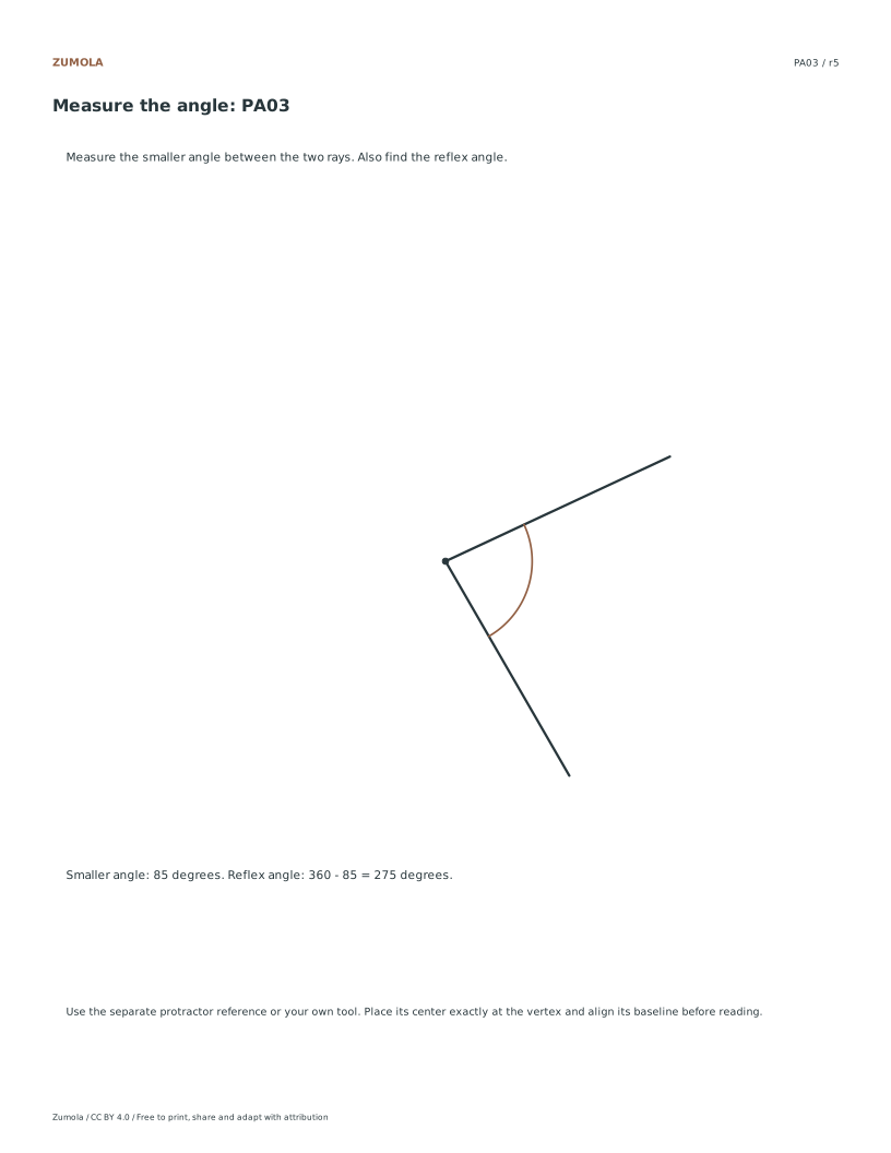
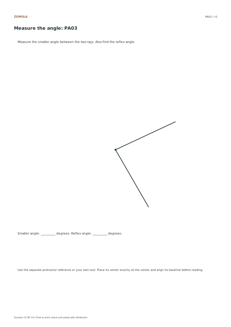
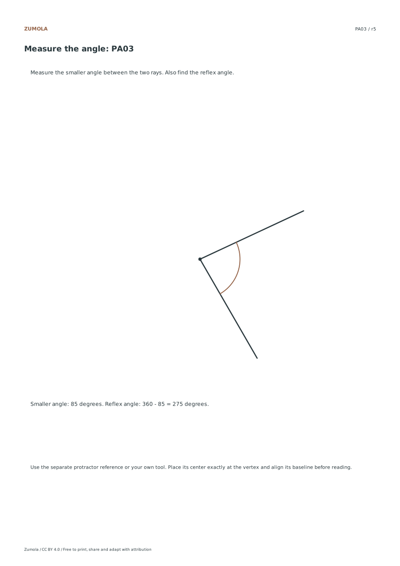
The 360° file marks 0° right, 90° up, 180° left and 270° down, increasing counterclockwise. To compare 300° with 25°, cross the zero direction: 60° + 25° = 85°. The reflex complement is 275°. Uniform resizing preserves angle geometry, but unequal stretching can change it. These templates have digital geometry checks and no physical calibration or precision-instrument certification.
Work through the page
Aligning the Baseline Correctly Place the center cross on the angle vertex. Align the zero direction with one of the rays before following the other ray to the degree ticks. The 180° template has a straight baseline; the 360° template marks a zero ray from the center toward the right. Keep the center fixed when rotating a protractor to match an angle. A shift in the center and a wrong choice of zero are different errors, so check them separately. If the print is stretched differently horizontally and vertically, the apparent angular distances can change even when its labels still look evenly ordered.
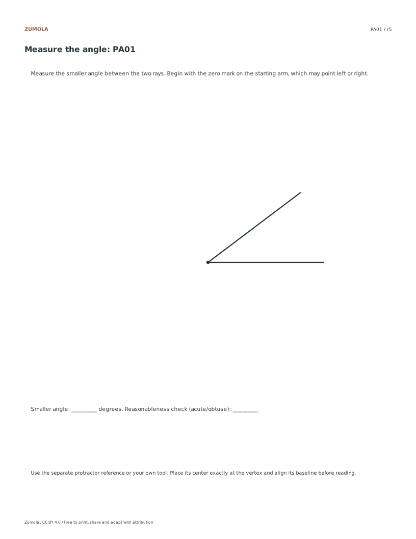
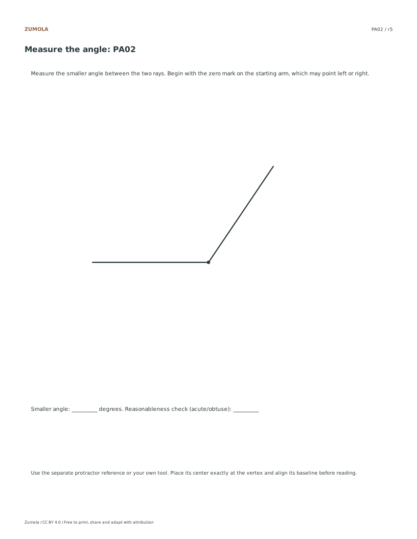
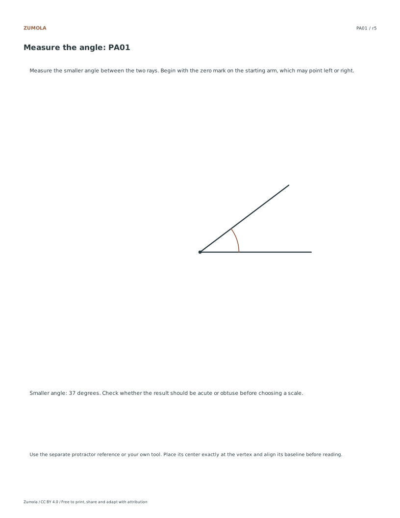
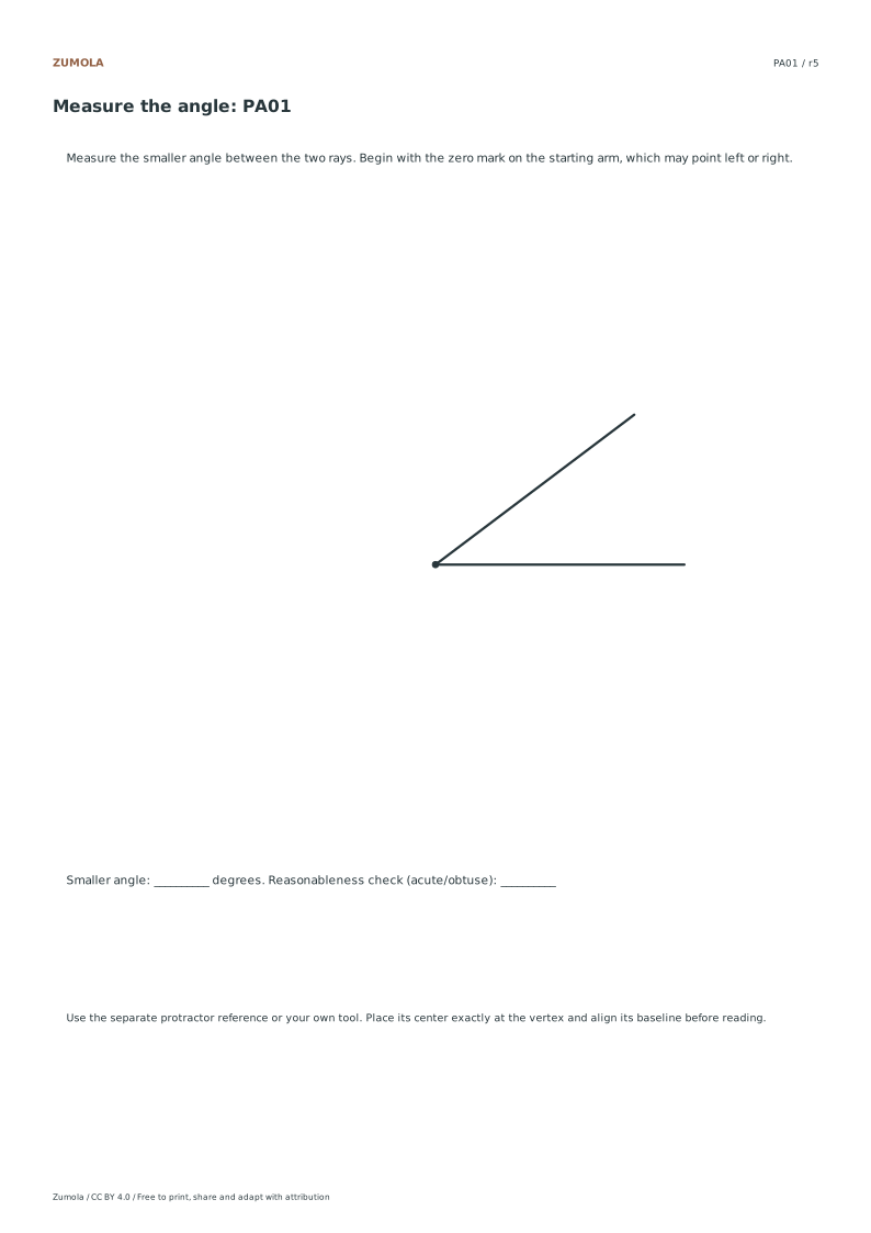
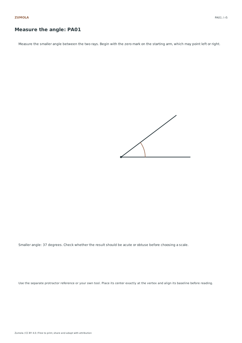
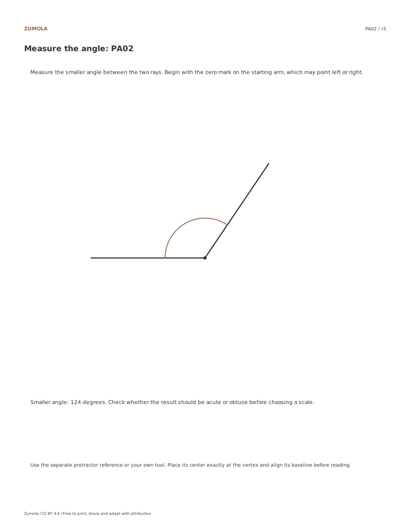
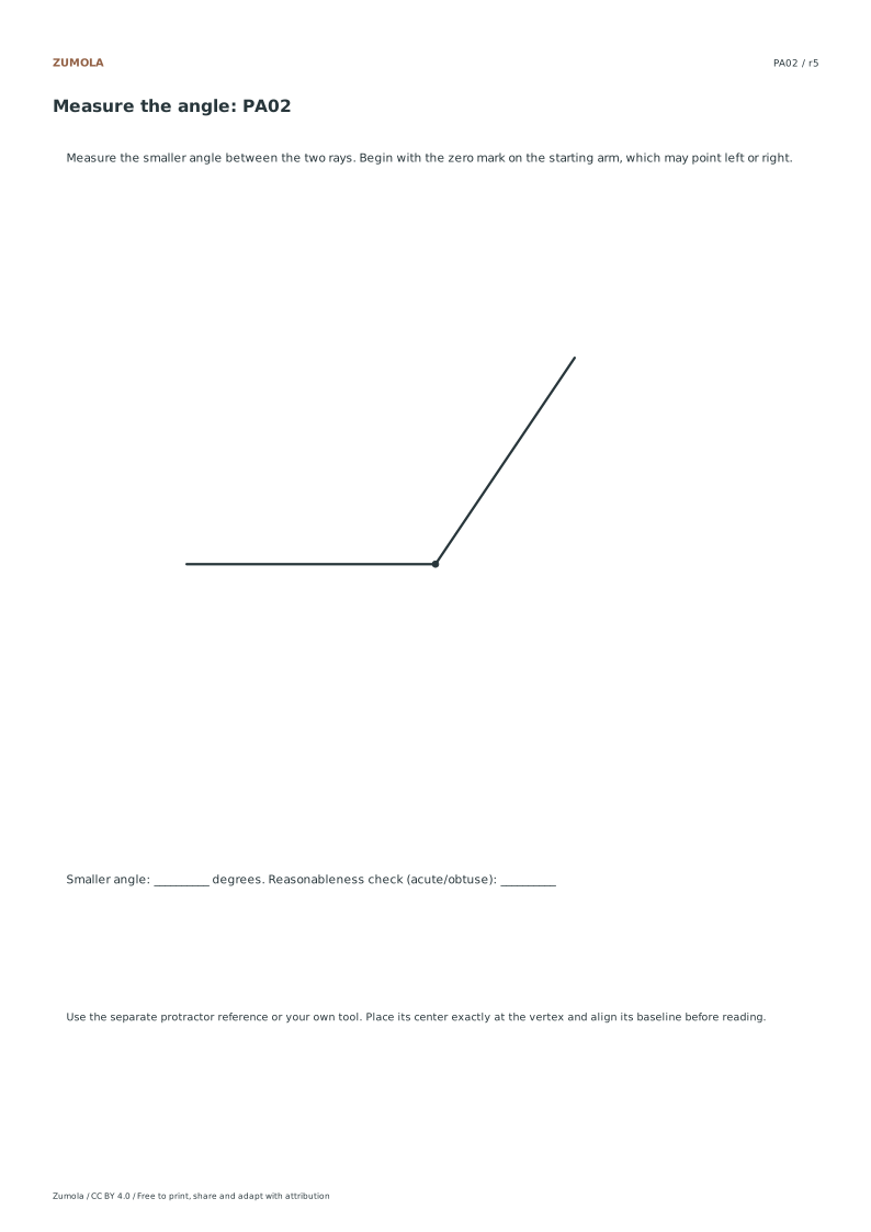
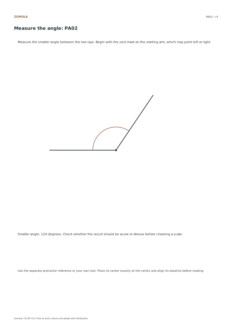
Reading the Correct Scale The semicircular template has two opposed scales. On this particular file, the outer scale reads 0° on the right and 180° on the left; the inner scale reverses that order. Those labels are not a universal rule for every commercial protractor. Follow whichever scale starts at zero on your chosen starting ray. PA01 starts on the right and ends at 37°, so it is acute. PA02 begins on the left and its other ray is at 56° measured from the right, giving 180° − 56° = 124°, an obtuse angle.
Verifying Print Accuracy Print the resource at one hundred percent scale to maintain geometric integrity. Uniform scaling preserves the accuracy of angles, but nonuniform horizontal or vertical distortion will alter the measured values. Use a standard paper size and avoid stretching the image during printing. Since the file is vector based, one degree ticks and ten degree labels remain sharp. Note that digital verification of tick and angle geometry has been completed, but physical printer tests have not been performed. Check that the center and baseline marks are clearly visible and correctly positioned relative to the scale numbers after printing.
Checks that catch common errors
Watch for
Check instead
Reading the outer scale when the baseline ray points to the left.
Use the inner scale which begins at zero on the left side for left-pointing baselines.
Assuming the outer scale always starts at zero on the right.
Check which scale begins at zero on the side where your baseline ray is aligned.
Printing with nonuniform horizontal or vertical scaling.
Print at one hundred percent to ensure uniform scaling preserves the correct angle geometry.
Match the file before printing
Print the PDF matching the paper in your printer at Actual size / 100% if you want to retain the millimeter dimensions defined in the file. Turn off Fit and Shrink when those dimensions matter. Uniform resizing preserves relative image proportions and angles but changes physical lengths. Unequal resizing can distort both. SVG editors and browser print dialogs can also change scale, so measure a physical calibration span when the task relies on size.
These files have digital geometry and layout checks. Physical printer testing has not been completed. Complete a student page before comparing the worked answer or reference illustration. A geometric or counting result can be exact, while a hand drawing can vary in its marks and interpretation. The original resources use CC BY 4.0: credit Zumola, link the license and indicate changes.
Useful answers
What happens with rays at 300° and 25°?
Move across 0°: 300° to 360° is 60°, then another 25° gives the smaller 85° angle. The reflex angle is 360° − 85° = 275°. The two ray directions are 300° and 25°, not one direction of 325°.
What is the reading for a right baseline to thirty seven degrees?
The reading is thirty seven degrees when the baseline is on the right and the ray points to thirty seven.
How do I read a left baseline to fifty six degrees from the right?
The reading is one hundred twenty four degrees when the baseline is on the left and the ray is at fifty six from the right.
Are the answers and editable files free too?
Yes. Every linked original worksheet, answer, PDF and SVG is free without signup. Individual SVG sheets stay editable; collection packs are PDF files. Analytics consent is not required to use the resources.
A protractor's radius sets how far its markings extend from the center point. It does not change the size of a degree. A 180-degree protractor with a larger radius gives longer arcs and finer spacing between degree marks, which can make reading easier, but the same angle measures the same on a smaller tool.
When you draw an angle to measure, keep the vertex exactly at the center mark and let one arm lie along the baseline. If the arms are longer than the tool's radius, extend the baseline and read where the second arm crosses the curved edge, or shorten the drawn arms so both fit inside the arc. Never slide the tool to reach a longer arm; moving the center changes the reading.
Place the center mark on the vertex and align the baseline with one arm.
Check that both arms fall within the tool's radius; if not, redraw shorter arms from the same vertex.
Identify which zero sits on the starting arm, then follow that scale only.
Read the degree where the second arm crosses the arc, and note whether the angle is acute, right, obtuse or reflex.
Choosing the inner or outer scale
Half-circle protractors usually carry two numbered scales running in opposite directions. The scale that begins at zero on your starting arm is the one to follow. If you begin on the right arm and the outer scale reads zero there, use the outer numbers; the inner scale would give the supplement instead.
For a reflex angle greater than 180 degrees, a half-circle tool cannot read it directly. Measure the smaller angle between the arms, then subtract that value from 360 degrees. For example, if the smaller angle is 110 degrees, the reflex angle is 360 minus 110, which is 250 degrees.
Mark which arm is your starting arm before reading.
Find the zero that touches that arm and stay on its scale.
For angles above 180 degrees, measure the smaller angle and subtract from 360.
Sanity-check: an acute reading should be under 90, an obtuse reading between 90 and 180.
A calibration and alignment check
Before trusting any measurement, confirm the print is at actual size. A calibration bar printed at 100 percent should measure its stated length with a ruler; if it does not, the scale is distorted and readings will drift. This is a print check, not a claim about any particular printer.
Alignment errors are the most common cause of wrong readings. A center mark slightly off the vertex, or a baseline that does not sit on the arm, shifts every degree value. Re-seat the tool and read again; if two readings differ, the alignment is the likely cause, not the angle.
Measure the calibration bar with a ruler and confirm it matches its labeled length.
Re-check that the center mark sits on the vertex, not beside it.
Confirm the baseline lies along the starting arm for its full length.
Read the angle twice; a stable reading suggests good alignment.
Try this example
A drawn angle has its vertex at the center mark and one arm along the baseline to the right. The second arm crosses the arc at the 65-degree mark on the scale that starts at zero on the right arm. What is the angle, and what is its reflex counterpart?
Show the worked explanation
The angle is 65 degrees, an acute angle, because the scale beginning at zero on the starting right arm reads 65 at the second arm. The reflex counterpart is 360 minus 65, which equals 295 degrees. Check: 65 is under 90, so acute is consistent; 295 is above 180, so reflex is consistent.
Common mistakes
Reading the scale that starts at zero on the wrong arm. Identify the starting arm first, then use only the scale whose zero touches it; the other scale gives the supplement.
Sliding the protractor so a long arm reaches the arc. Keep the center on the vertex and shorten or extend the drawn arms instead of moving the tool.
Treating a half-circle reading as a reflex angle. Measure the smaller angle and subtract it from 360 degrees to get the reflex value.
Check your work
Center mark is placed on the vertex and the baseline lies along the starting arm.
The scale chosen begins at zero on the starting arm, not the opposite arm.
The reading is classified correctly as acute, right, obtuse or reflex.
Reflex angles are computed as 360 minus the smaller measured angle.
The calibration bar is checked before measurements are trusted.
A second reading is taken to confirm alignment stability.
Questions before you start
Does a larger protractor radius improve accuracy?
It can make marks easier to read because spacing is wider, but the degree value of an angle does not change with radius. Alignment matters more than size.
How do I measure an angle larger than 180 degrees with a half-circle protractor?
Measure the smaller angle between the two arms, then subtract that number from 360 degrees. The result is the reflex angle.
Why do my two readings disagree?
The usual cause is misalignment: the center mark is off the vertex or the baseline is not on the starting arm. Re-seat the tool and read again.
Optional Google Analytics helps us understand which free resources are useful. It is off until you allow it. Drawing tools and downloads work with either choice. Privacy details