Reference diagrams
LETTER · Download PDF
A4 · Download PDF
Free original resources
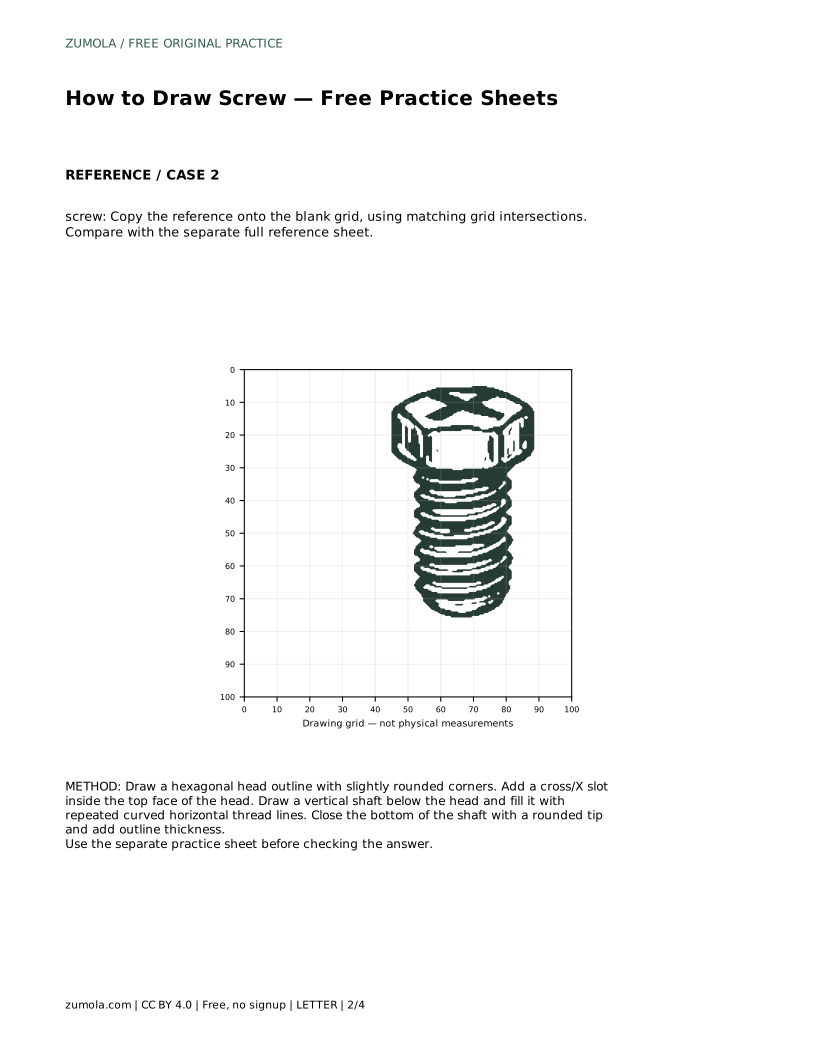
Learn to draw a screw with a hexagonal head, cross slot, threaded shaft, and rounded tip. Use tracing, grid, and frame guides to build the contour and details.
Four original cases, with reference diagrams, practice sheets and worked answers. Everything is free; no signup required.
LETTER · Download PDF
A4 · Download PDF
LETTER · Download PDF
A4 · Download PDF
LETTER · Download PDF
A4 · Download PDF
Use A4 or US Letter to match your printer. Use the stated values and conditions to solve each exercise; diagrams are not physical measuring rulers.
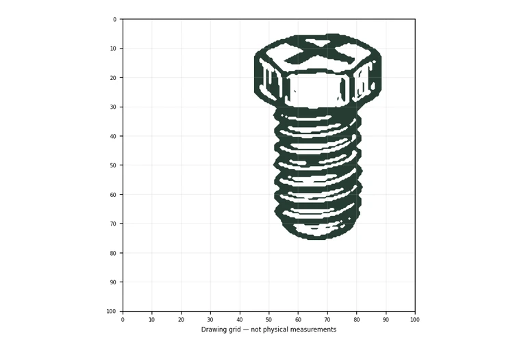
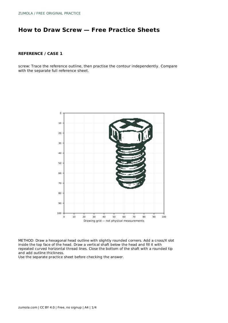
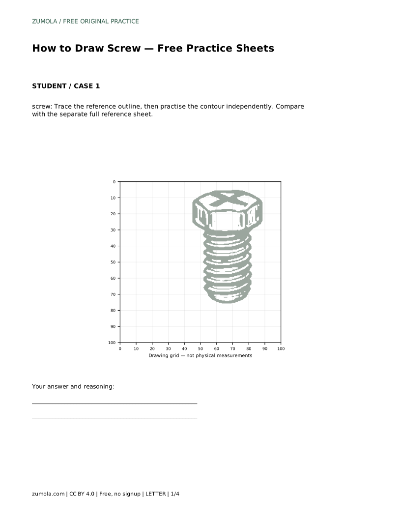
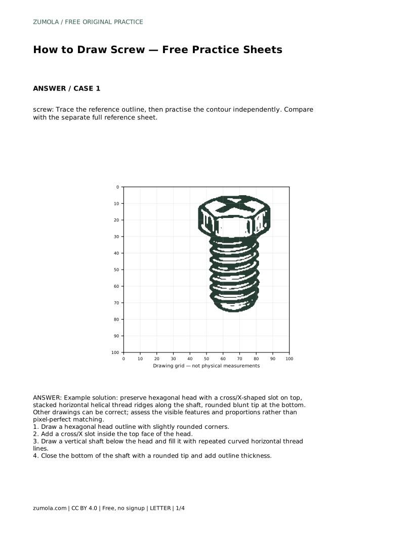
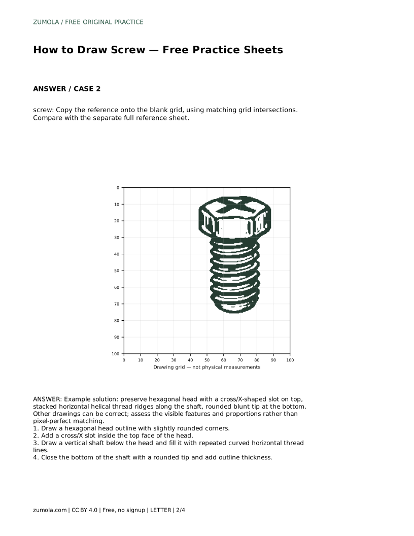
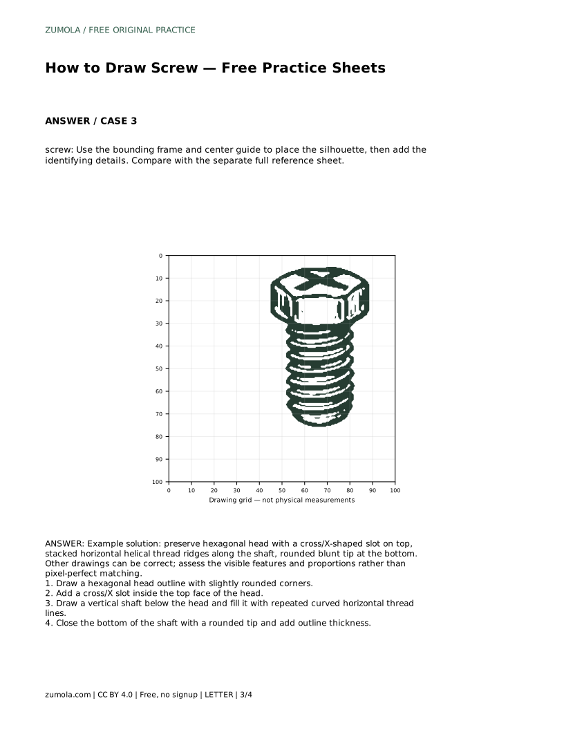
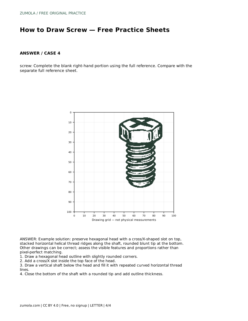
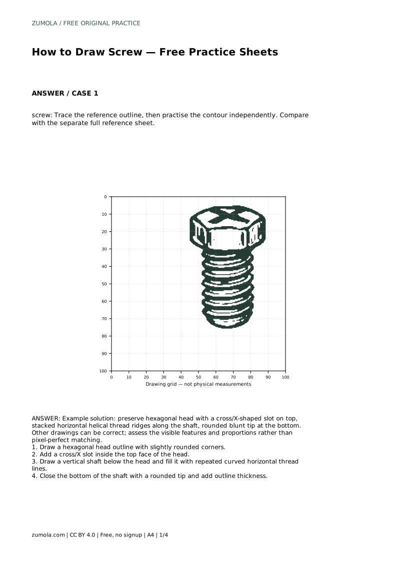
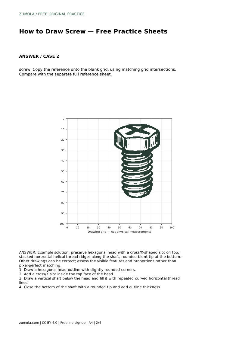
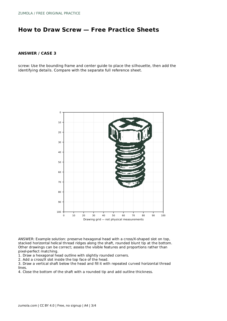
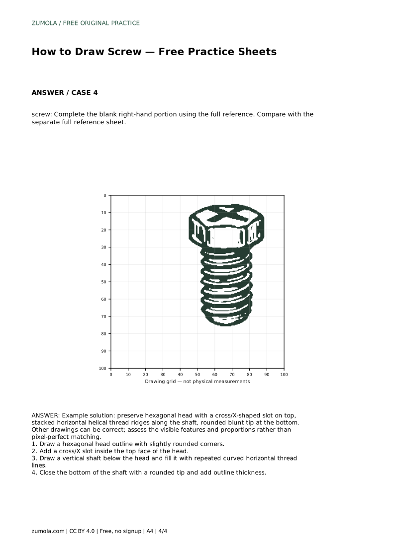
Drawing a screw is a useful exercise in combining simple geometry with repeated detail. The head is a rounded hexagon, the slot is a cross or X on the top face, and the shaft carries stacked curved thread lines that suggest a helix. This page explains how to place the silhouette, add the identifying features, and judge your drawing by visible structure rather than pixel-perfect matching. The practice sheets offer tracing, grid, frame, and partial-completion formats, each with a separate full reference for comparison.
Begin by drawing the hexagonal head as a flattened shape with slightly rounded corners. Keep the top face wide enough to hold a cross or X slot. The slot should sit inside the head outline, not on its edge. Draw the slot with two crossing lines that meet near the center; the lines can be slightly curved to suggest depth, but keep them clear and simple.
Check that the head reads as a solid shape before moving down. A common error is making the head too narrow or too tall, which makes the slot cramped. Compare the head width to the shaft width: the head should be noticeably wider than the shaft, but not so wide that it looks like a separate object.
Draw a vertical shaft below the head, centered under the slot. The shaft should be straight and roughly parallel-sided. Fill it with repeated curved horizontal lines to represent thread ridges. These lines are not perfectly horizontal; they curve slightly to suggest the helical path of a thread. Space them evenly, and keep the curves consistent from top to bottom.
The thread lines should stop before the very bottom of the shaft, leaving room for a rounded blunt tip. Close the bottom with a curve rather than a sharp point. Add outline thickness by drawing a second line just inside the outer contour, or by darkening the main outline. This helps the screw read as a solid object rather than a flat diagram.
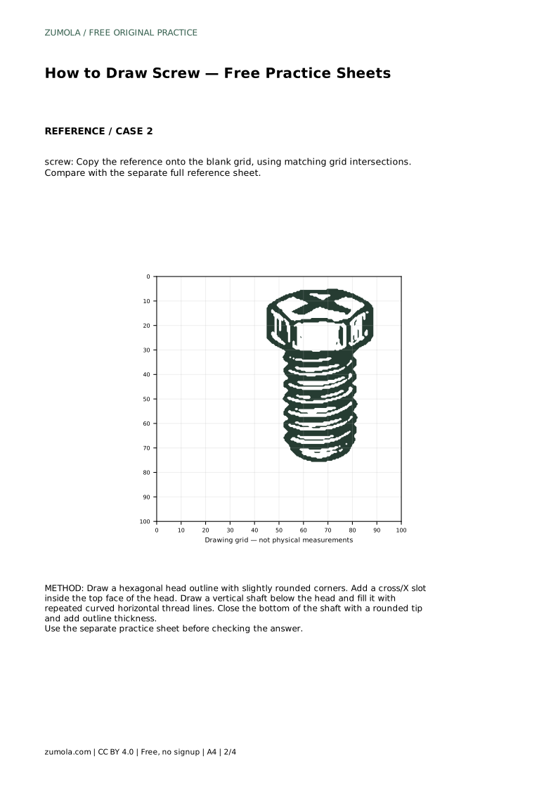
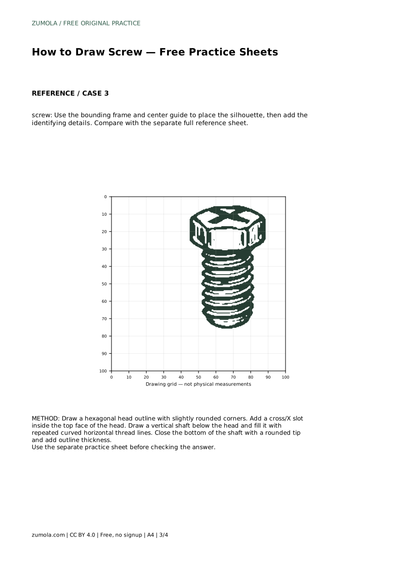
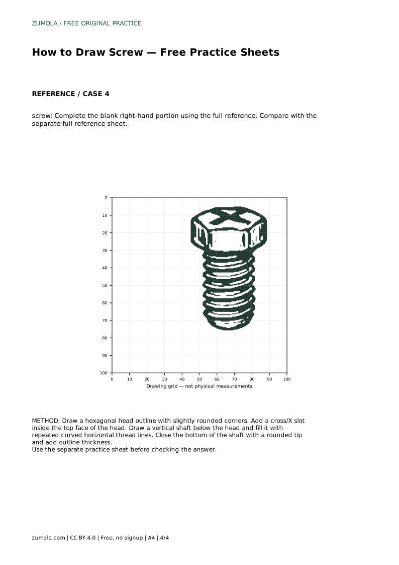
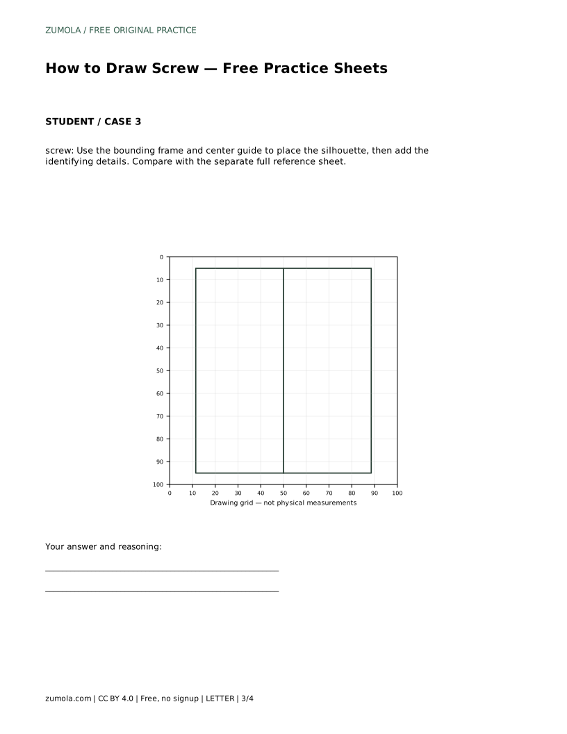
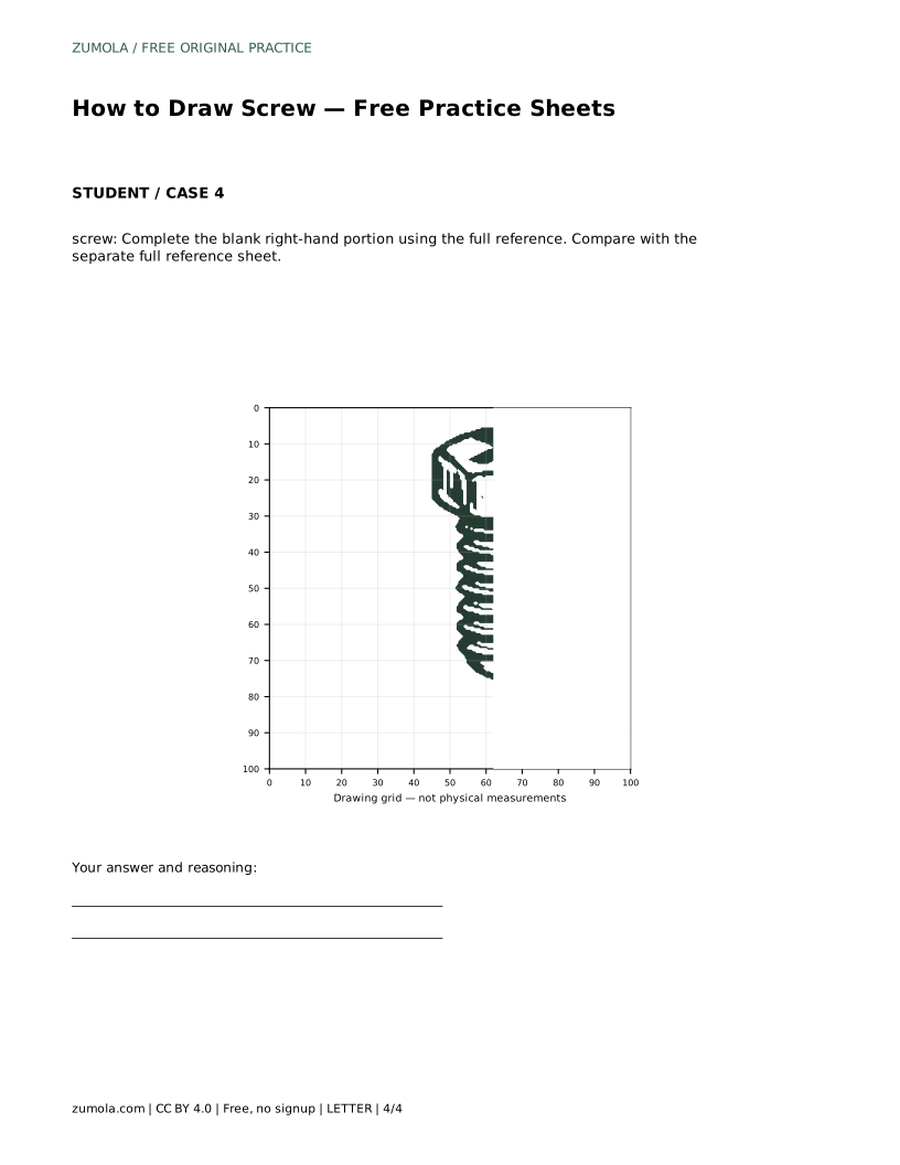
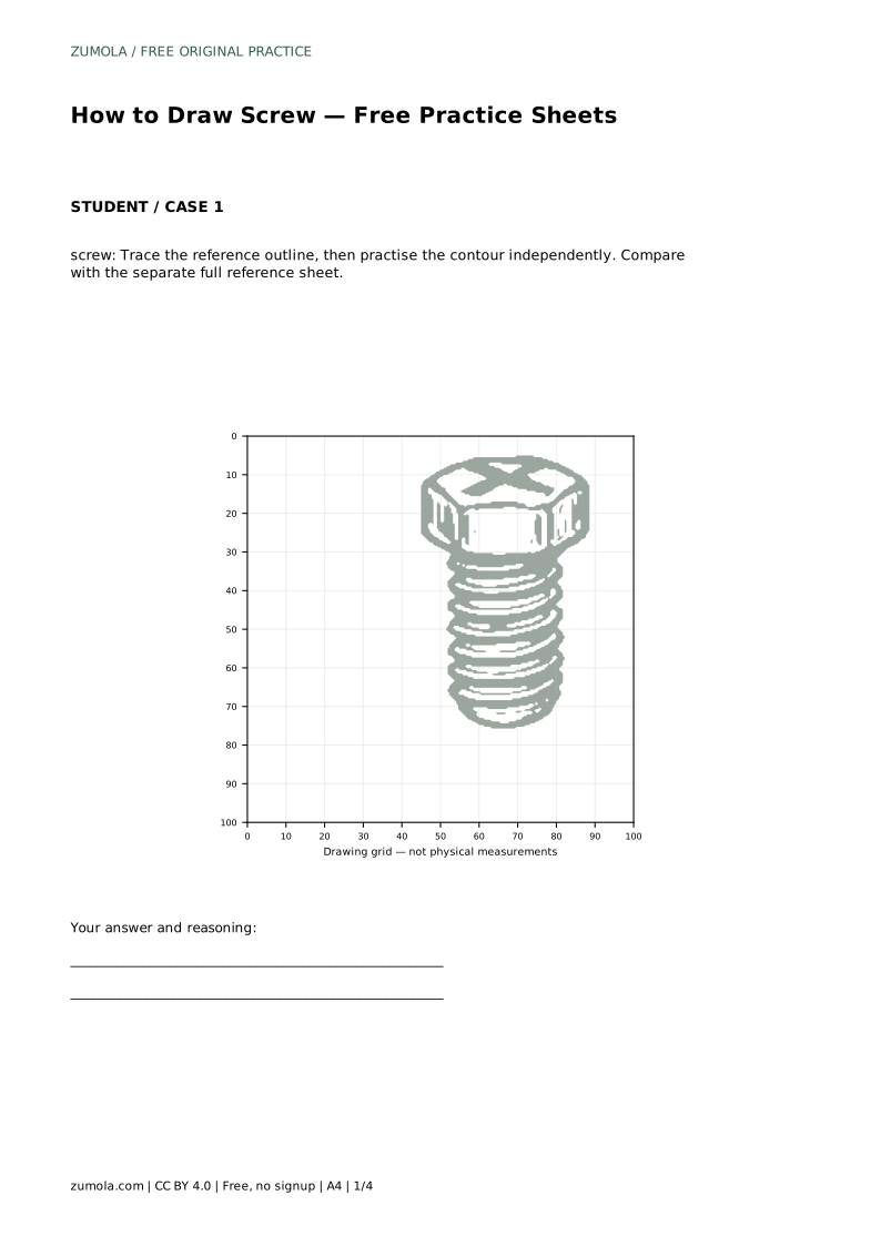
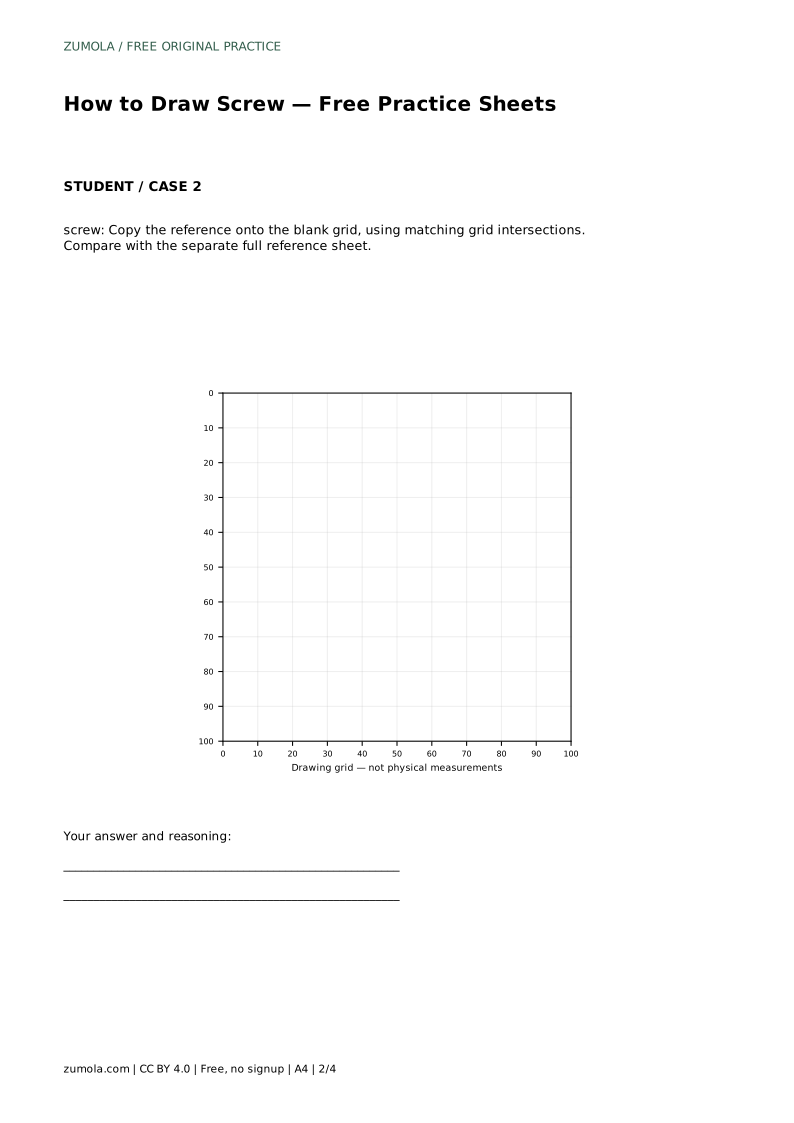
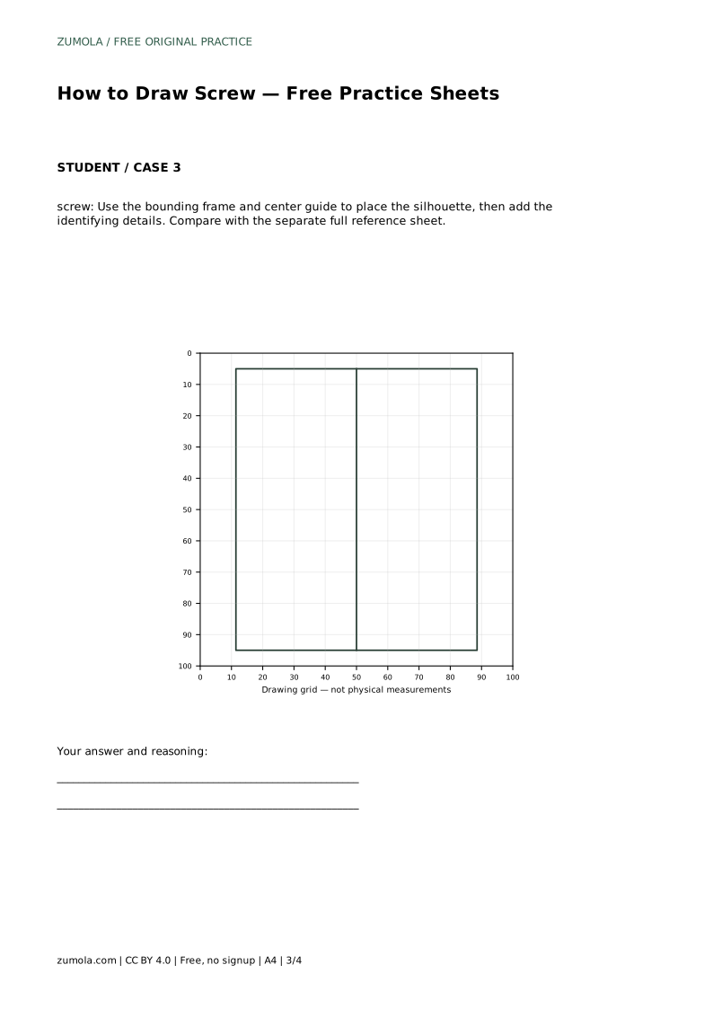
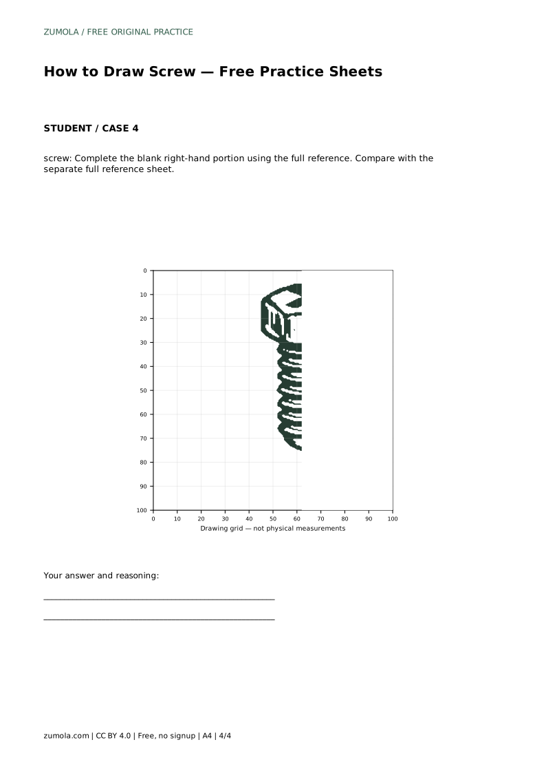
The tracing format asks you to follow the reference outline first, then practise the contour independently. The grid format asks you to copy the reference onto a blank grid using matching grid intersections. The frame format gives you a bounding frame and center guide to place the silhouette before adding details. The partial-completion format gives you the left portion and asks you to complete the right-hand portion using the full reference.
In each format, compare your drawing with the separate full reference sheet after you finish. Look for the hexagonal head, the cross or X slot, the stacked thread ridges, and the rounded tip. Other drawings can be correct; assess the visible features and proportions rather than pixel-perfect matching.
screw: Trace the reference outline, then practise the contour independently. Compare with the separate full reference sheet.
Example solution: preserve hexagonal head with a cross/X-shaped slot on top, stacked horizontal helical thread ridges along the shaft, rounded blunt tip at the bottom. Other drawings can be correct; assess the visible features and proportions rather than pixel-perfect matching. Draw a hexagonal head outline with slightly rounded corners. Add a cross/X slot inside the top face of the head. Draw a vertical shaft below the head and fill it with repeated curved horizontal thread lines. Close the bottom of the shaft with a rounded tip and add outline thickness.
Either is acceptable. The key is that the slot sits inside the top face of the head and reads as a single recessed feature.
There is no fixed count. Space them evenly and keep the curves consistent; the number can vary as long as the shaft reads as threaded.
The grid is a placement aid. Match the main intersections for the head and shaft, then adjust details by eye and compare with the full reference.
All drawing practice · Free coordinate paper
Original resources · CC BY 4.0 · Free for personal and classroom use with attribution.