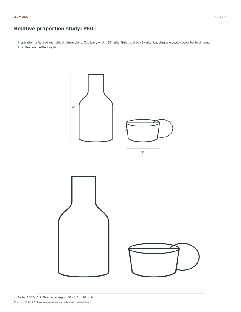
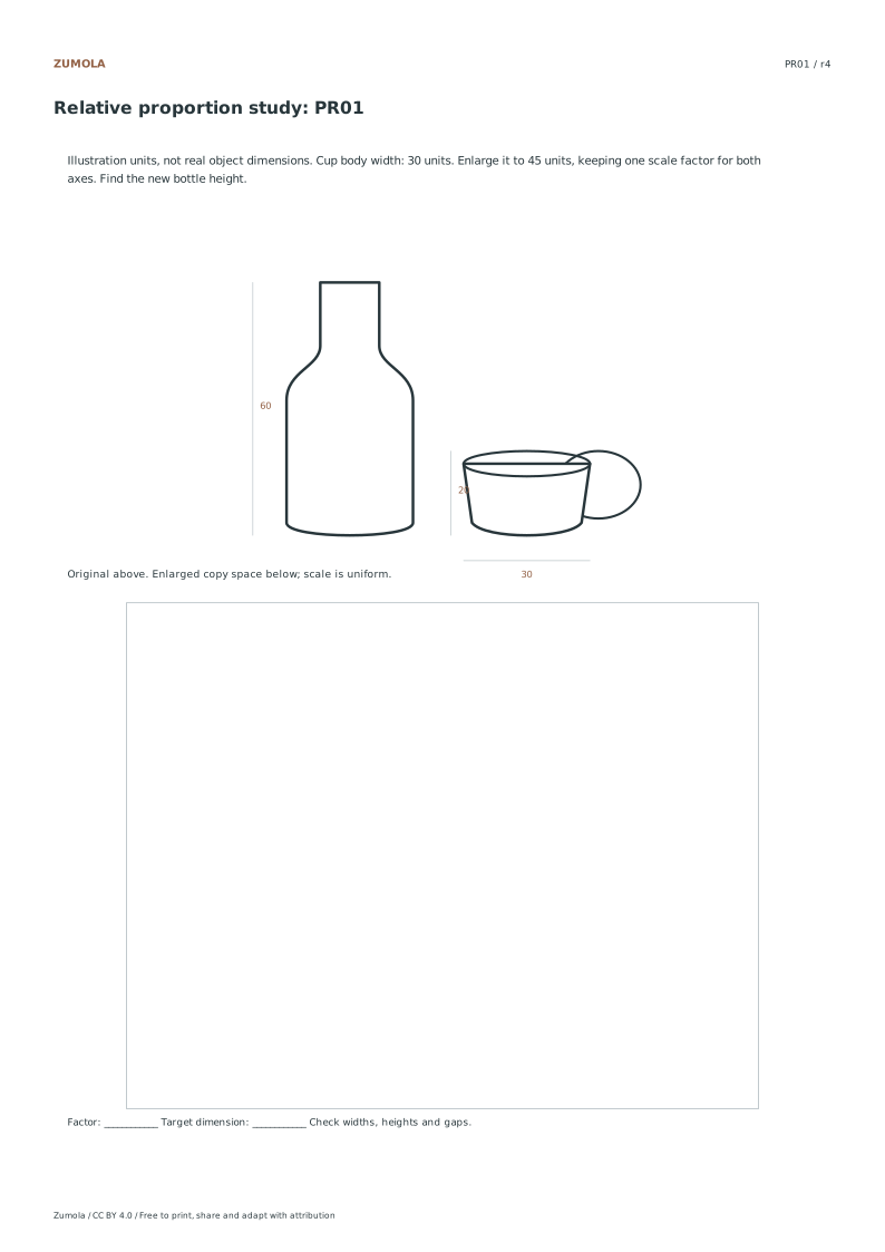
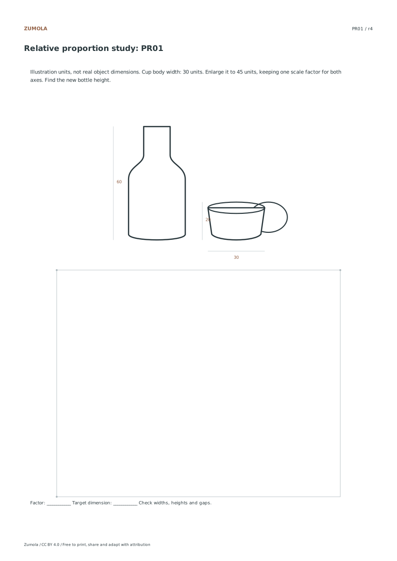
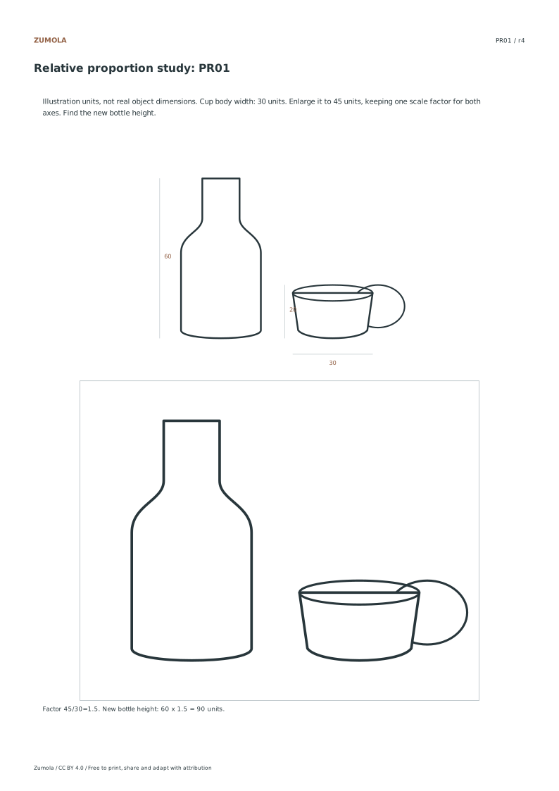
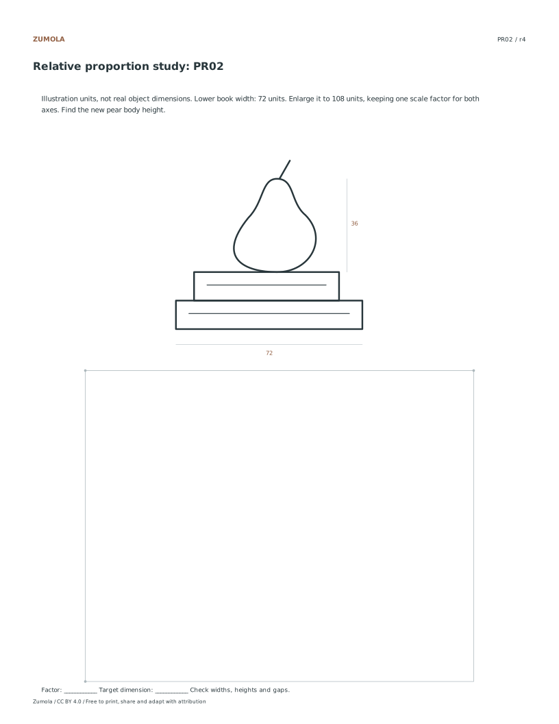
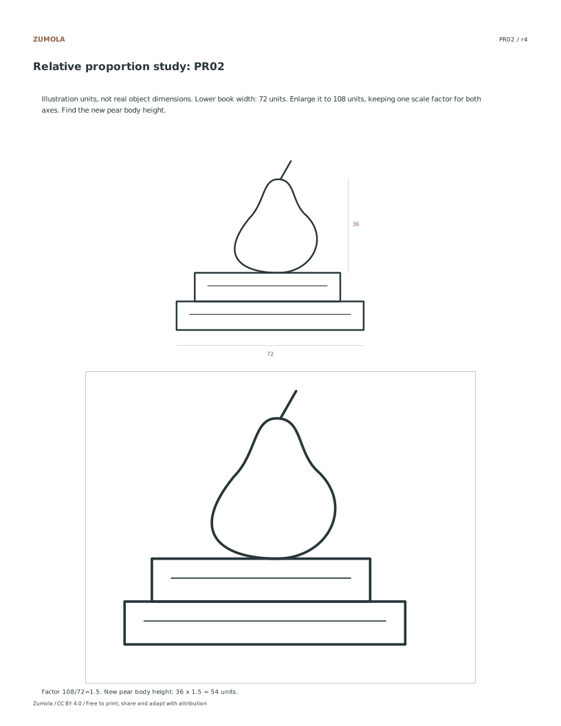
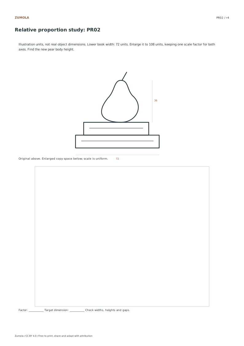
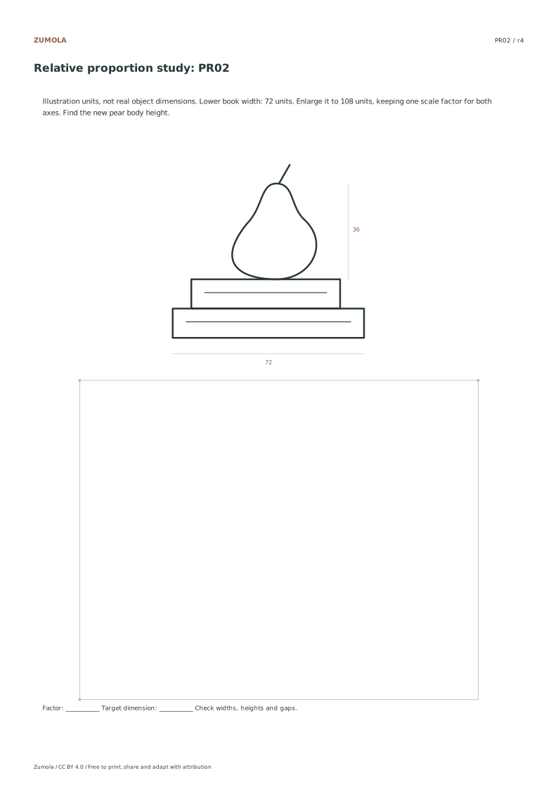
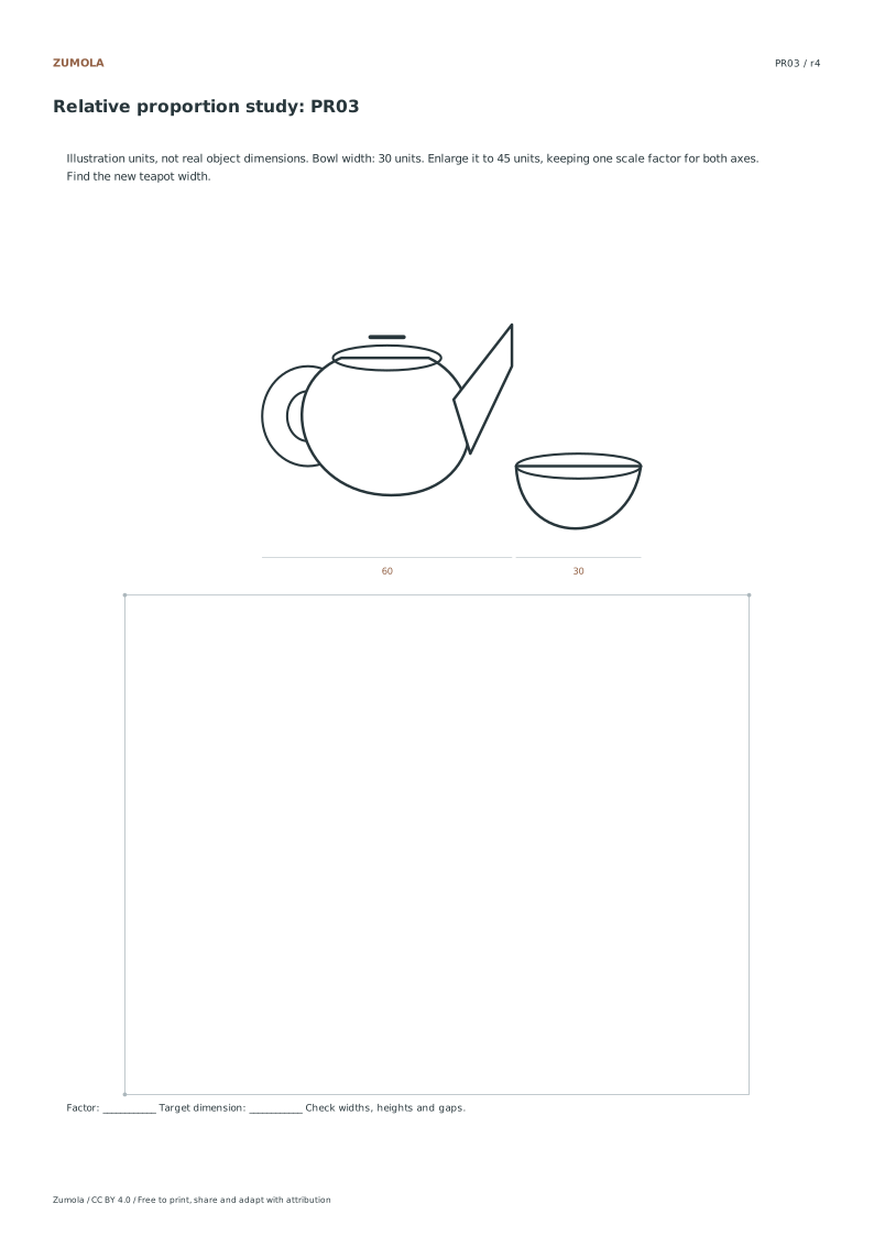
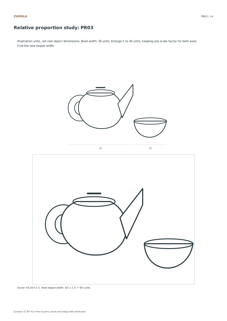
Use a labeled image feature as a measuring unit. Enlarge the same illustration uniformly while preserving relative heights, widths and gaps.
Choose US Letter or A4, then use the PDF for printing or SVG for editing. Student worksheets and answer or reference files stay separate. Every linked file is free without signup.
Choose your paper and download
Download paper size
Every worksheet and answer is free. No signup.
The complete collection
Keep practice and answers separate.
Use the student pack first, then compare the reference or answer. Packs are PDFs; individual sheets below also include editable SVG files. The paper choice applies to every download.
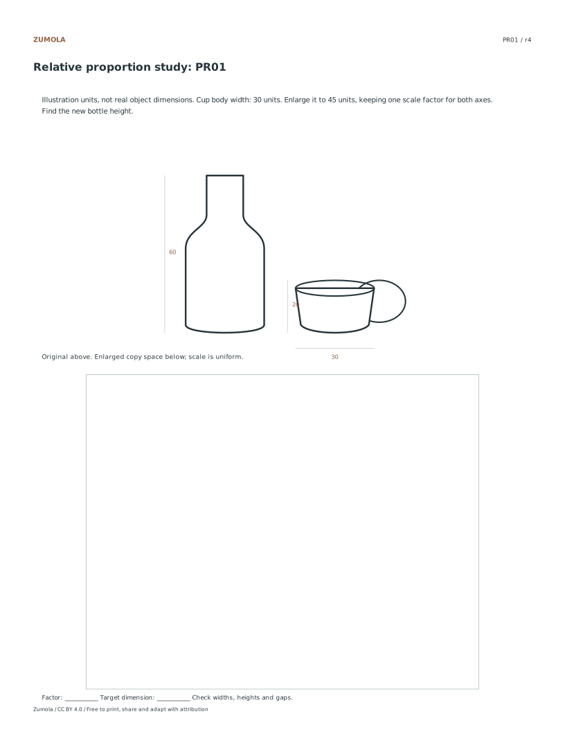
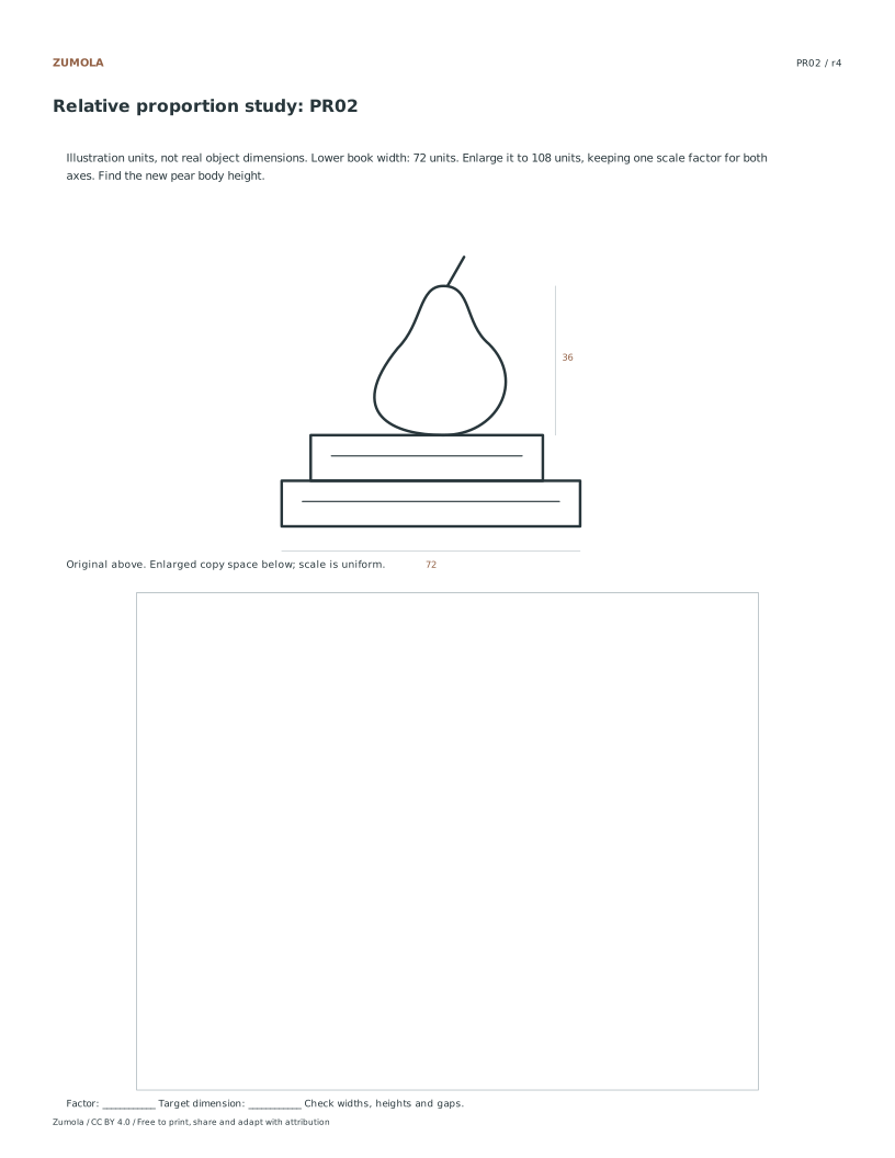
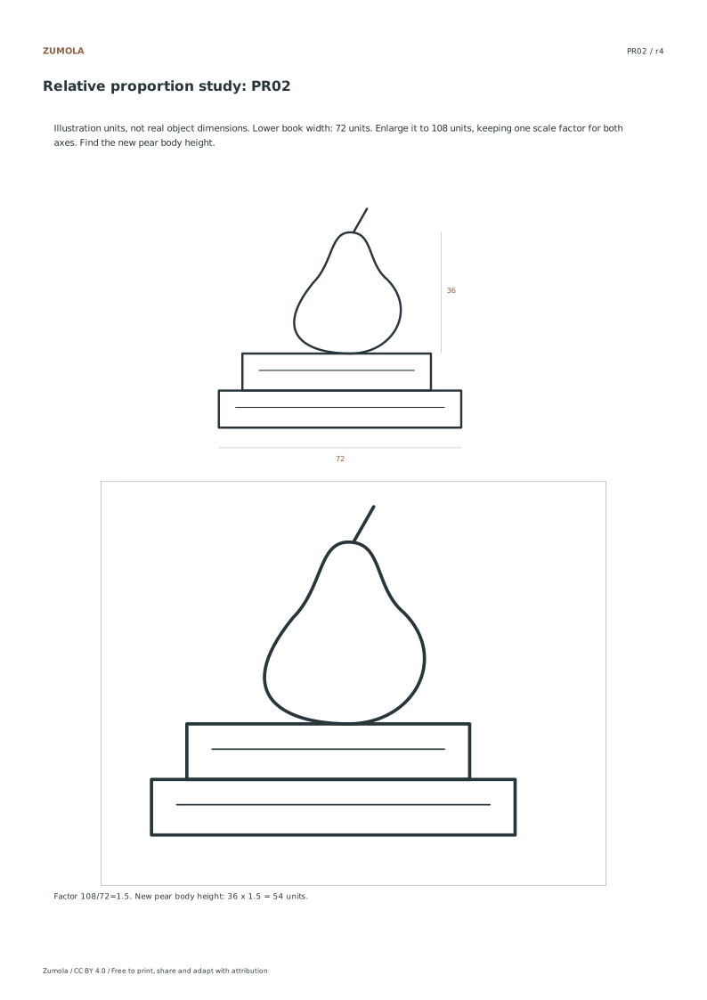
The cup body width excludes its handle. The pear body height excludes its stem. Those definitions keep the measured feature clear. A label is an image unit, not a claim about the dimensions of a real cup, pear or teapot. The original illustration uses a 100 × 80 unit canvas; the target frame is a uniform 150 × 120 enlargement.
For an image point (x,y), the enlarged local position is (1.5x,1.5y). The physical page placement adds an offset, but that does not change relative dimensions. Apply the same factor to the gap between two objects and to each object’s width and height. The reference also helps you notice a width that looks plausible alone but no longer agrees with its neighboring feature.
Work through the page
Identify Reference Landmarks
Begin by examining the reference image for each study, such as the bottle and cup or books and pear. Locate specific labeled landmarks that define the vertical and horizontal extents of the measured image features. Measure the distance between these points in units rather than inches or centimeters. For instance, note that the bottle height is sixty units while the cup’s full height is twenty units. The 30-unit cup width refers to its body, excluding its handle. In PR02 the 36-unit pear body height excludes its stem. This establishes a three to one ratio. Record these measurements carefully because they serve as the foundation for calculating the enlarged dimensions. Accurate identification of these relative widths and heights ensures that the subsequent scaling process maintains the correct proportions of the original line-based illustration without relying on real world object sizes.
Calculate Enlargement Factors
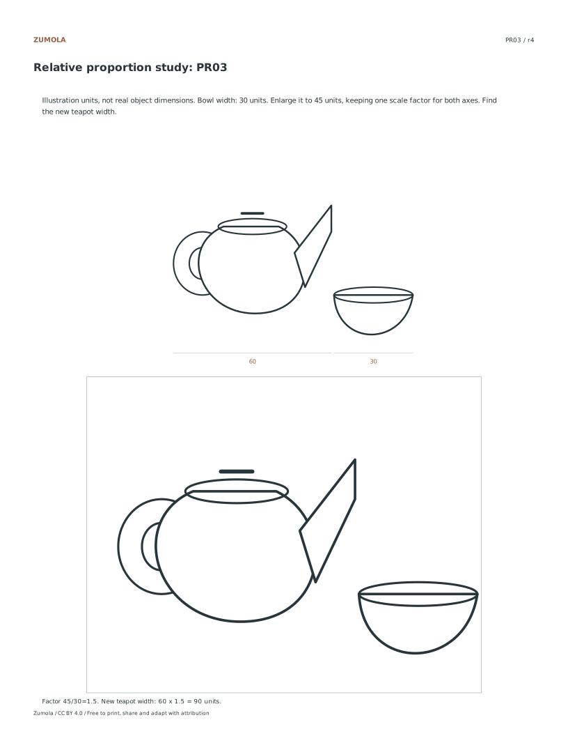
Determine the scaling factor by comparing the target dimensions to the reference measurements. If the target width for the cup body is forty five units and the reference width is thirty units, the enlargement factor is one point five. Apply this same factor to all corresponding dimensions to maintain aspect ratio. For the bottle, multiply the reference height of sixty units by one point five to get a target height of ninety units. Ensure that the factor is identical for both horizontal and vertical axes. This uniform scaling preserves the gaps between objects and the relative positions of landmarks, ensuring the final drawing is a precise mathematical enlargement of the original illustration rather than a distorted representation.
Transfer to Student Copy Box
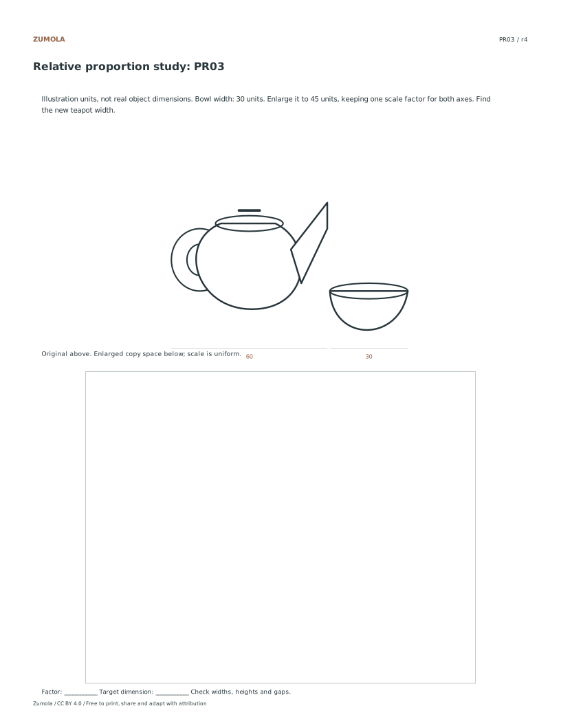
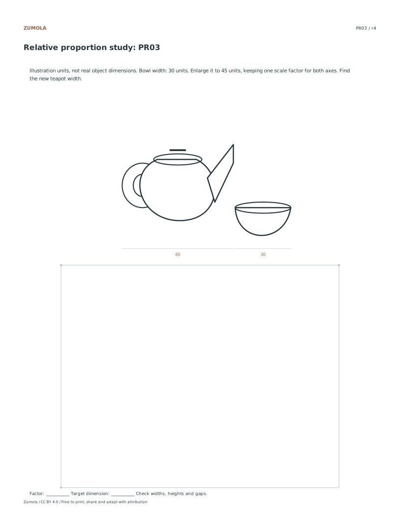
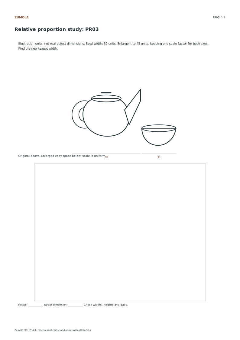
Use the calculated target dimensions to guide your drawing within the student copy box. Start by marking the overall height and width based on the enlarged measurements, such as ninety units for the bottle height. Lightly sketch the bounding boxes for each object using the relative widths and heights derived from the reference. Focus on maintaining the exact image ratios as checks for accuracy. Do not attempt to replicate natural perspective or physical object sizes. Instead, concentrate on preserving the spatial relationships and landmark positions defined in the original line-based study. This method ensures that the teapot and bowl or books and pear maintain their correct proportional relationships in the enlarged format.
Checks that catch common errors
Watch for
Check instead
Using real world measurements instead of unit ratios
Measure distances in arbitrary units from the reference image and apply the scaling factor to these units, ignoring actual physical sizes of bottles or books.
Applying different scaling factors for width and height
Use the same enlargement factor, such as one point five, for both horizontal and vertical dimensions to preserve the original aspect ratio and landmark positions.
Assuming natural perspective accuracy
Treat the exact image ratios as proportional checks only, recognizing that the line-based studies do not claim to represent natural still-life perspective or physical object proportions.
Print a test sheet before the full pack
Choose the file matching the paper in your printer. Print the PDF at Actual size / 100%, turning off Fit, Shrink and browser headers. An SVG editor or browser can change its scale even though the file uses millimeter dimensions. Use the supplied calibration bars where present when a task depends on physical size; a screen preview alone does not establish printed size.
The packs contain the same individual pages in collection order. They are a convenient download, not extra different exercises. On coordinate plots, uniform scaling preserves the numerical positions relative to the axes. On image-copy tasks, keep the specified proportions and any stated source-to-target enlargement. Color is optional: labels, line positions and relative lightness also explain the references.
Useful answers
What is the enlargement factor for the teapot and bowl study?
The enlargement factor is one point five. The reference teapot width is sixty units and the bowl width is thirty units. If the target bowl width is forty five units, the teapot target width becomes ninety units.
How do I determine the target height for the cup?
Identify the reference cup height of twenty units and the reference bottle height of sixty units. If the target bottle height is ninety units, the cup target height is thirty units, maintaining the three to one ratio.
Are the printed images accurate to real object sizes?
No. These are original line illustrations with stated image landmarks. The cup-body width excludes its handle, and the pear-body height excludes the stem. The ratios describe these pictures, not universal sizes of real objects.
Are the answers and editable files free too?
Yes. Every linked worksheet, PDF, SVG and answer is free without signup. Original Zumola resources use CC BY 4.0: credit Zumola, link the license and indicate changes. Analytics consent is not required to download or use them.
Length ratios answer how many times one feature fits into another. Angles answer direction: the tilt of an edge, a gap between two lines, or the slope from one landmark to another. Negative shapes answer the space between parts, such as the gap under an arm or between two fingers. Record all three because a drawing can match a length ratio while still looking wrong when an angle or gap is off.
Use one anchor feature as the measuring unit, as in the existing task. Then add two angle notes and two negative-shape notes. Keep units explicit: lengths in anchor units, angles in degrees estimated from a straight edge or protractor, and gaps as a fraction of the anchor. Do not mix paper millimetres with image units.
Place the reference beside the practice sheet, not underneath it.
Mark the anchor feature and write its length as 1 unit.
Estimate two angles with a straight edge; record each to the nearest 5 degrees.
Trace or describe two negative shapes and compare their widths to the anchor.
Recheck one length ratio, one angle and one gap before revising.
A diagnostic pass before revising
A diagnostic pass separates observation errors from drawing errors. First compare your notes with the reference: did you record the angle in the right direction, and did you measure the gap between the correct landmarks? Only then compare the drawing to the notes. If the notes are wrong, correcting the drawing will not help.
Treat the reference as a teaching image with clear steps, not as a clinical anatomy diagram. Facial proportion studies describe visible relationships in a drawing; they do not establish medical facts about skull structure. Multiple valid outcomes are expected, so judge the quality of comparison and correction rather than exact replication.
Check each recorded angle against the reference direction.
Confirm each negative shape sits between the intended landmarks.
Compare the drawing to your notes, not directly to the reference.
List one correction and apply only that change.
Repeat the diagnostic pass once.
Keeping records useful
Write short comparison notes beside each study: anchor unit, two angles, two gaps, and one correction. Date the sheet and note the reference used. This makes later practice comparable without relying on memory. Keep answer or reference material separate from the practice sheet so the comparison stays honest.
If you enlarge the reference, enlarge it uniformly and keep the anchor unit consistent. A non-uniform enlargement changes angles and gaps, so angle notes from the original no longer apply.
Label the anchor unit at the top of the sheet.
Record angles and gaps in a small table.
Note the single correction made.
Store the reference separately from the practice sheet.
Try this example
A reference shows a vertical anchor of 4 grid squares. An edge tilts 30 degrees from vertical, and a gap between two parts is 1 grid square wide. Your drawing uses a 6-square anchor. What should you record and check?
Show the worked explanation
The anchor ratio is 6 divided by 4, or 1.5. The gap should be about 1.5 grid squares in the drawing if the enlargement is uniform. The 30-degree tilt stays 30 degrees because uniform enlargement preserves angles. Record the anchor as 1 unit, the tilt as 30 degrees, and the gap as 0.25 anchor units, then compare the drawing to those notes before revising.
Common mistakes
Measuring angles from a stretched or non-uniformly enlarged reference. Enlarge uniformly, or take angle notes only from the original reference.
Comparing the drawing directly to the reference while ignoring recorded notes. Run the diagnostic pass: check notes first, then compare drawing to notes.
Mixing paper millimetres with image units in the same ratio. Express all lengths as multiples of one anchor feature and state the unit.
Check your work
Anchor feature is labeled and used consistently as one unit.
Two angles are recorded to the nearest 5 degrees with direction noted.
Two negative shapes are described between named landmarks.
Length ratios, angles and gaps use stated, consistent units.
The diagnostic pass checks notes before comparing the drawing.
One specific correction is listed and applied.
Reference material is kept separate from the practice sheet.
Questions before you start
Do I need a protractor for angle notes?
No. A straight edge and an estimate to the nearest 5 degrees is enough for comparison practice; a protractor improves consistency if you have one.
What counts as a negative shape here?
Any enclosed or partly enclosed space between parts of the reference, such as a gap between two limbs or between a feature and an outline.
Can two drawings both be correct?
Yes. Proportion exercises compare observation records; different valid drawings can match the same recorded lengths, angles and gaps within reasonable tolerance.
Optional Google Analytics helps us understand which free resources are useful. It is off until you allow it. Drawing tools and downloads work with either choice. Privacy details