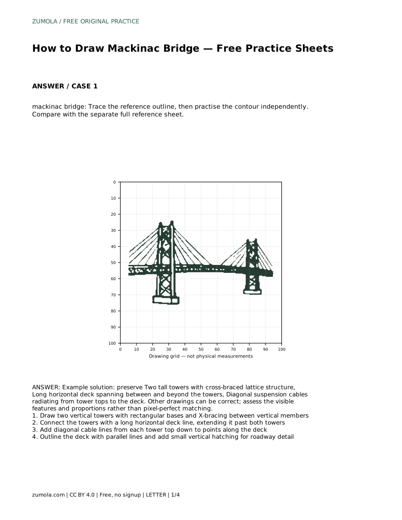
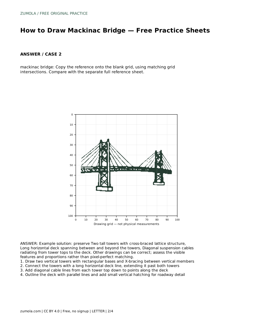
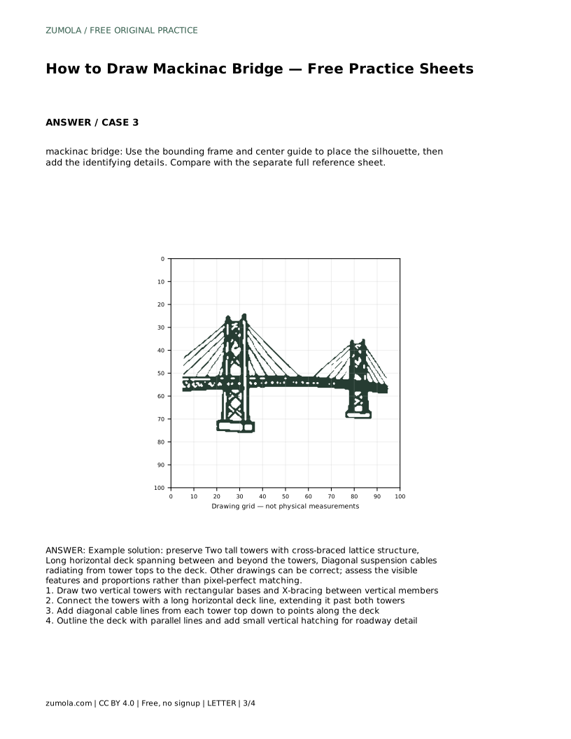
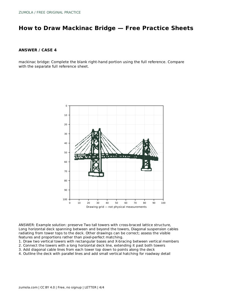
Reference diagrams
LETTER · Download PDF
A4 · Download PDF
Free original resources
Learn to draw the Mackinac Bridge by placing two braced towers, a long deck and radiating suspension cables. Free printable practice sheets support each stage.
Four original cases, with reference diagrams, practice sheets and worked answers. Everything is free; no signup required.
LETTER · Download PDF
A4 · Download PDF
LETTER · Download PDF
A4 · Download PDF
LETTER · Download PDF
A4 · Download PDF
Use A4 or US Letter to match your printer. Use the stated values and conditions to solve each exercise; diagrams are not physical measuring rulers.
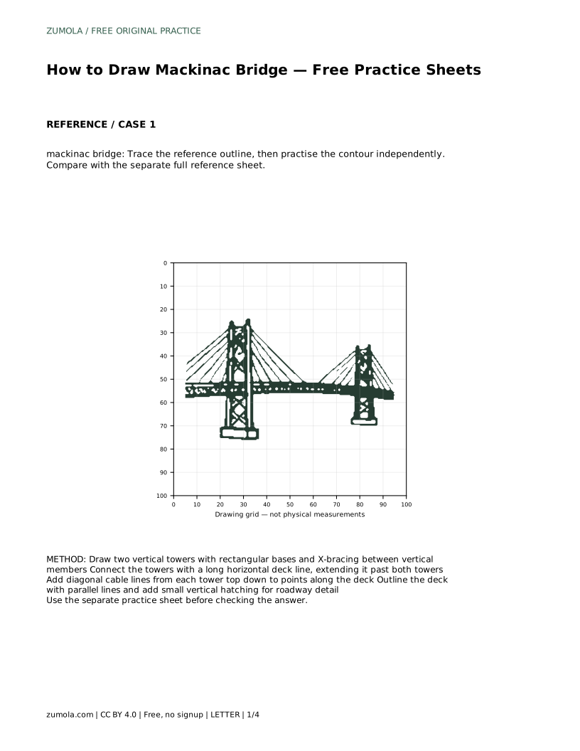
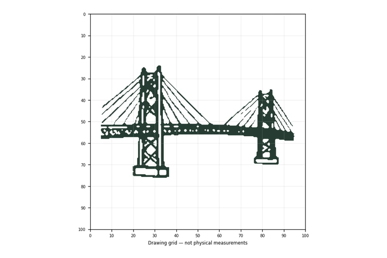
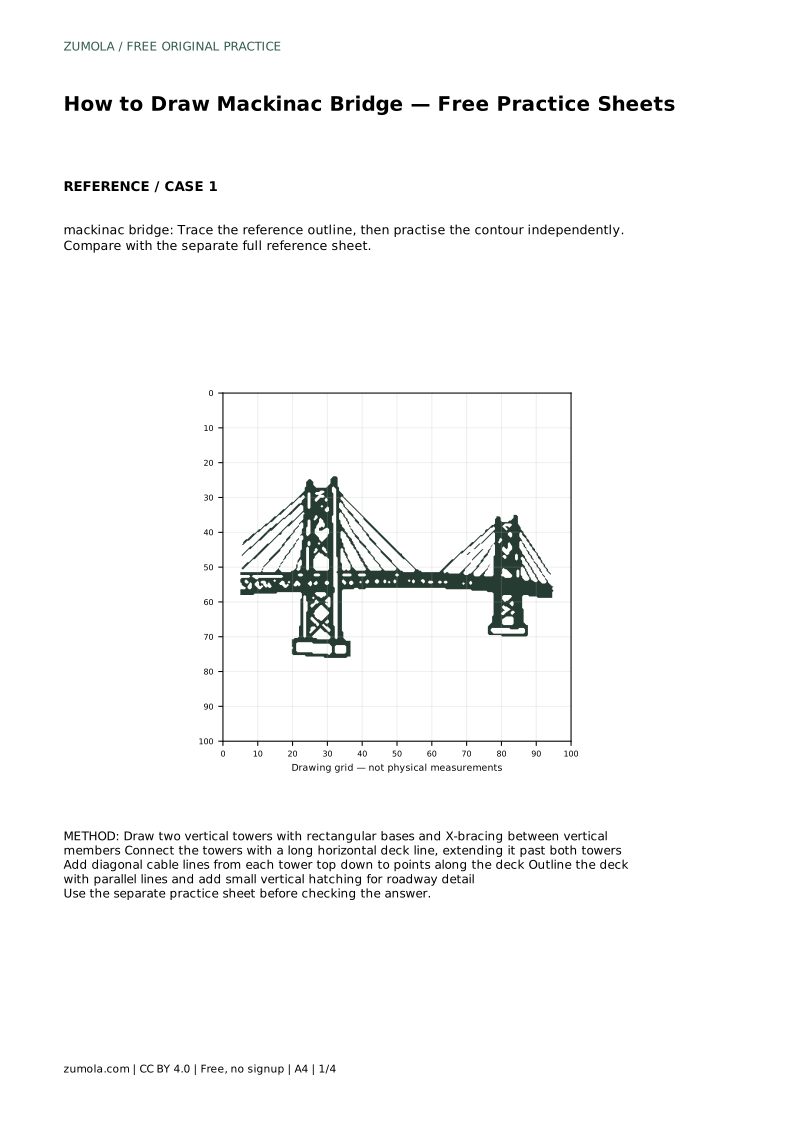
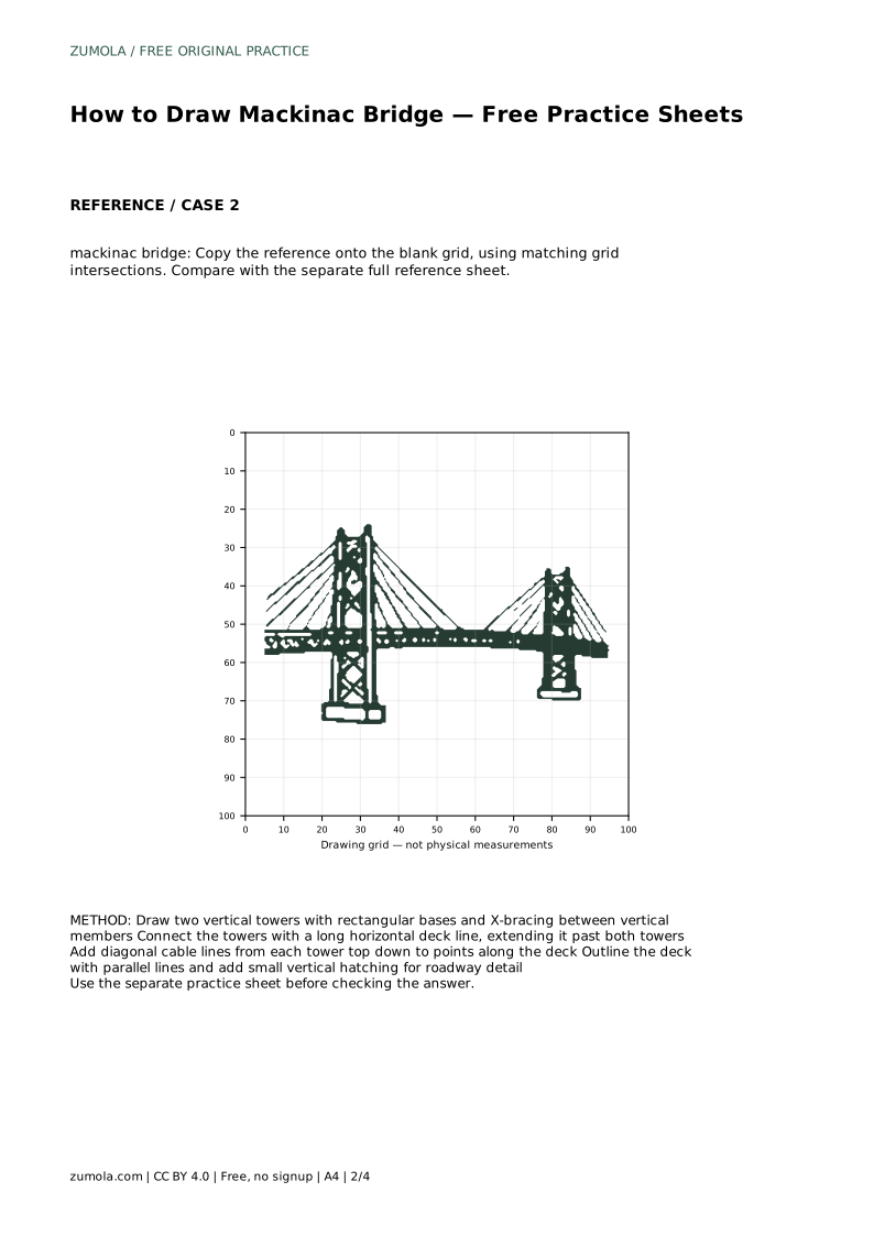
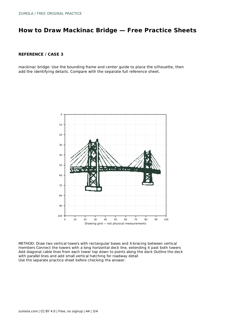
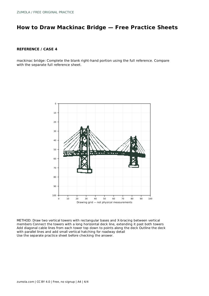
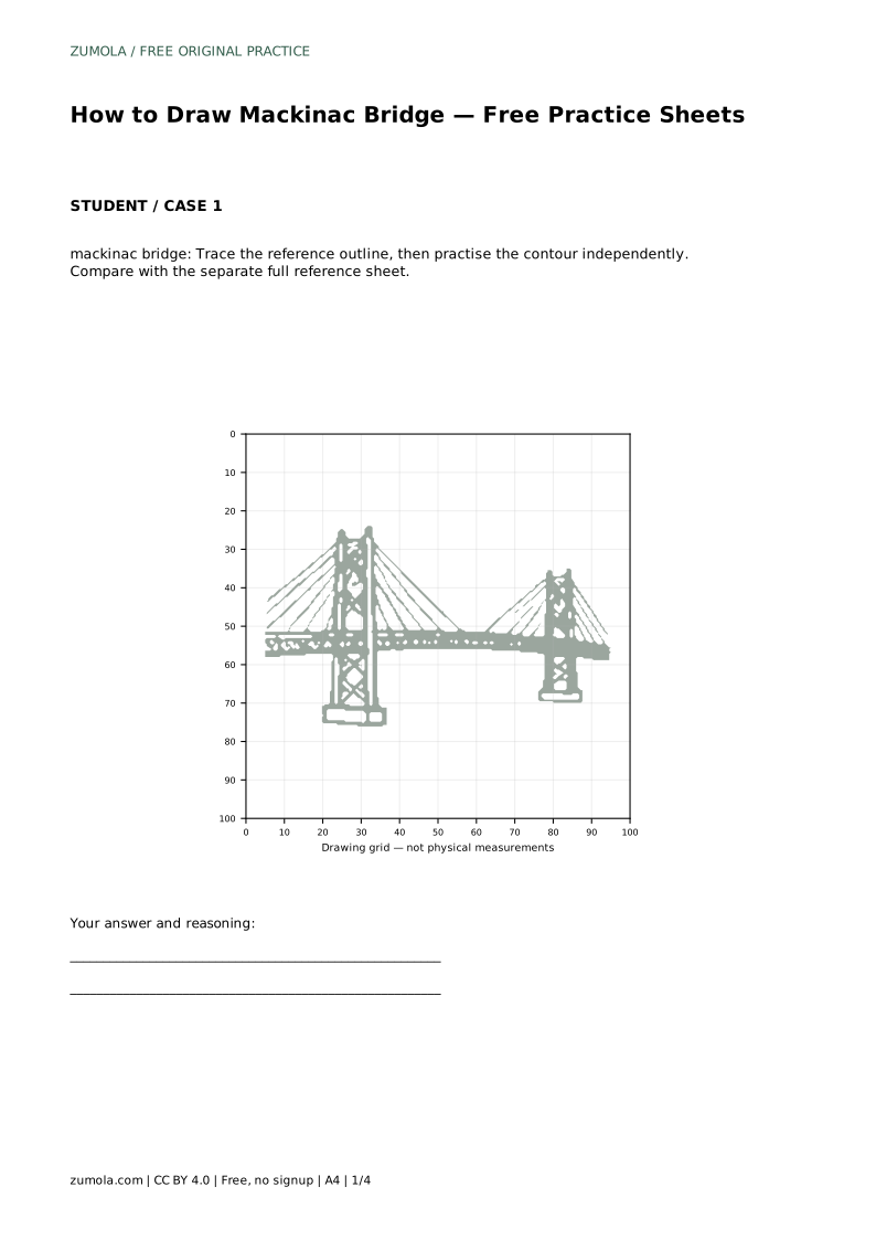
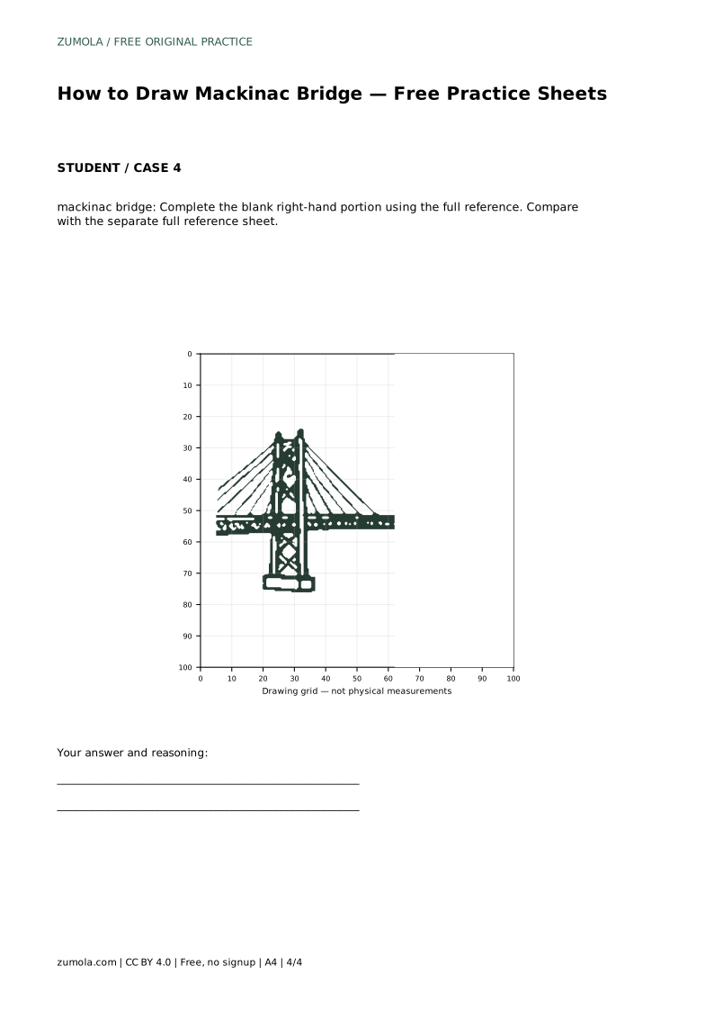
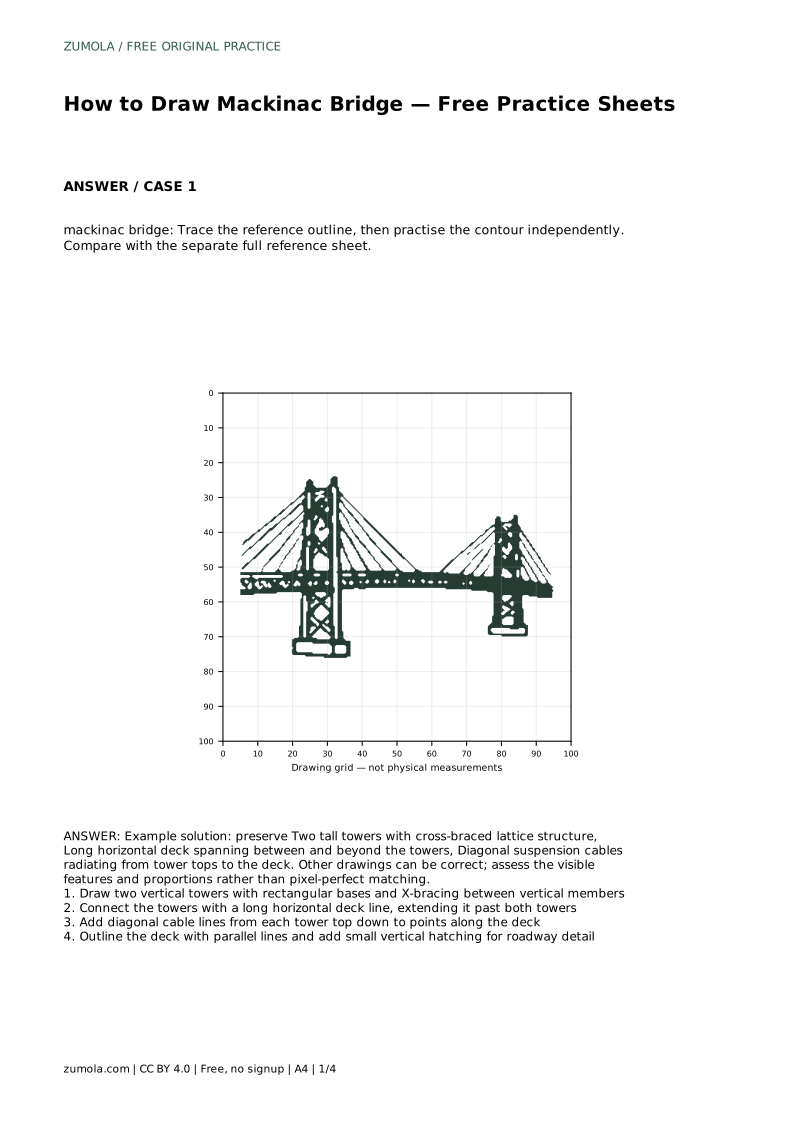
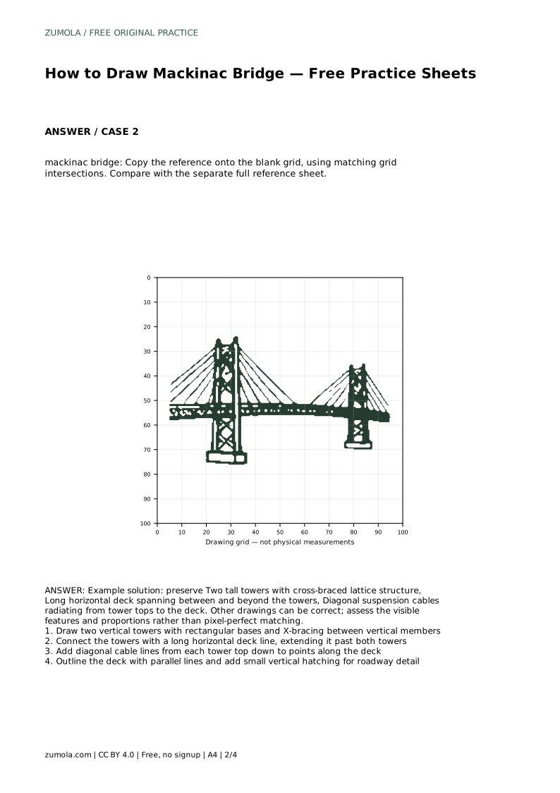
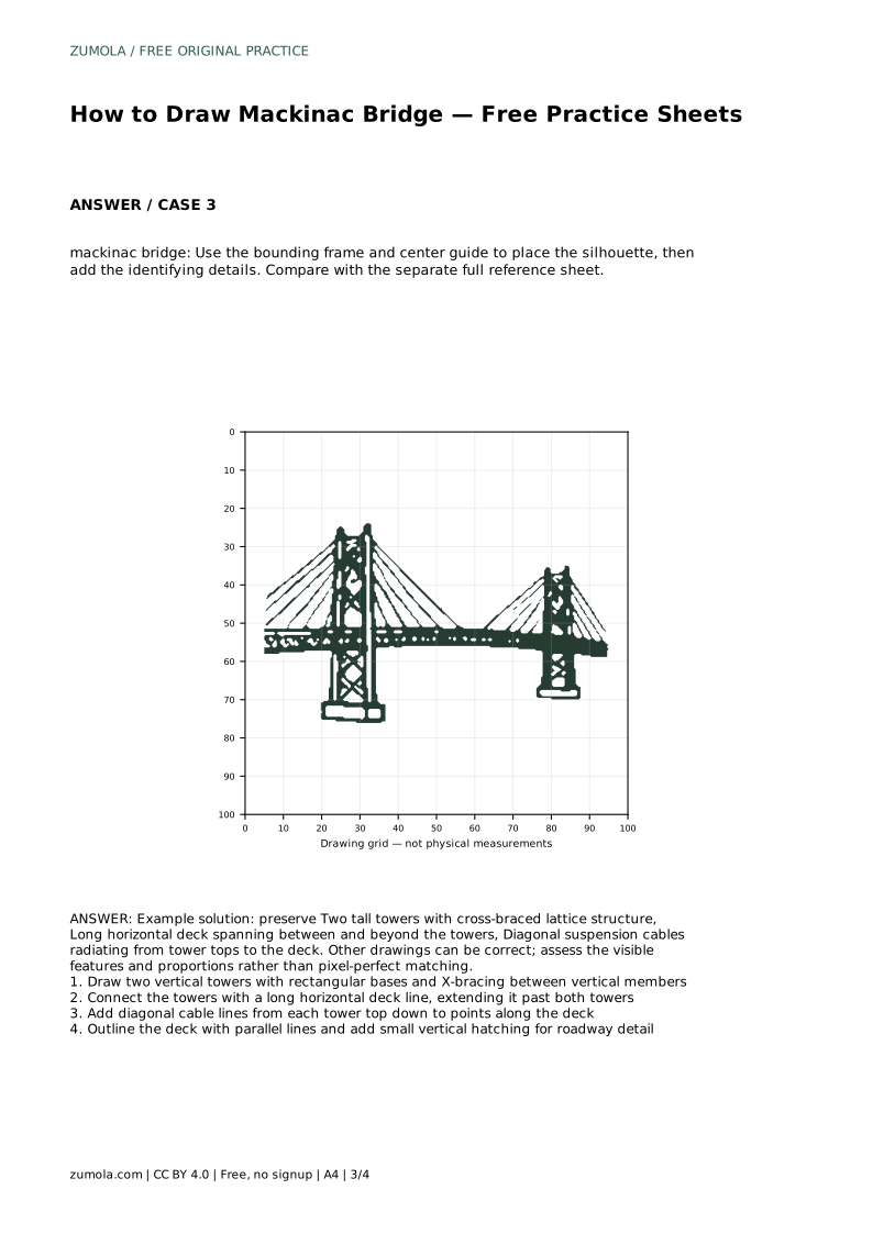
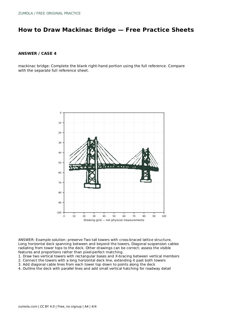
The Mackinac Bridge is recognisable by three features: two tall towers with cross-braced lattice sides, a long horizontal deck that runs between and beyond those towers, and diagonal suspension cables that fan from each tower top down to the deck. This page shows how to build those features in order, from tower placement to cable detail, so your drawing reads clearly as this bridge rather than a generic suspension bridge.
Begin by deciding where the two towers sit on your page. They should be vertical, roughly equal in height, and spaced far enough apart that the deck between them looks long. Draw each tower as a narrow rectangle first, then add a slightly wider rectangular base so the tower appears to meet the water or ground rather than float.
Inside each tower, add the cross-bracing: vertical members running up the tower, with diagonal lines crossing between them to form a lattice. Keep the bracing consistent on both towers so they look like a matched pair. This lattice is one of the clearest identifying details, so give it enough space to be visible rather than cramming it into a thin strip.
Draw a long horizontal line connecting the two towers at deck level. Extend that line past both towers on each side, because the roadway continues beyond the suspended section. This extension matters: a deck that stops exactly at the towers looks cut off and loses the bridge's long, low profile.
Once the main deck line is placed, outline it with a second parallel line to give the roadway thickness. Add small vertical hatching along the deck to suggest roadway detail. Keep the hatching light and even so it reads as texture rather than as a second structure.
From the top of each tower, draw diagonal cable lines down to points along the deck. The cables should radiate outward from the tower top, spreading toward the deck on both sides of each tower. Draw them as a set of straight lines rather than curves, since suspension cables run taut between anchor points.
Work one tower at a time so the cable pattern stays balanced. Check that cables from the left tower and the right tower mirror each other reasonably well. The cables should meet the deck, not stop in mid-air, and they should not cross the tower lattice in a confusing tangle.
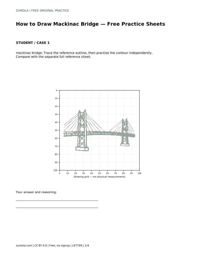
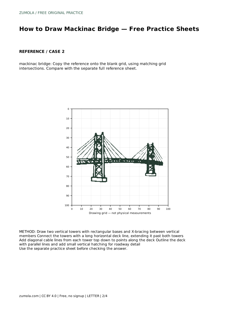
mackinac bridge: Trace the reference outline, then practise the contour independently. Compare with the separate full reference sheet.
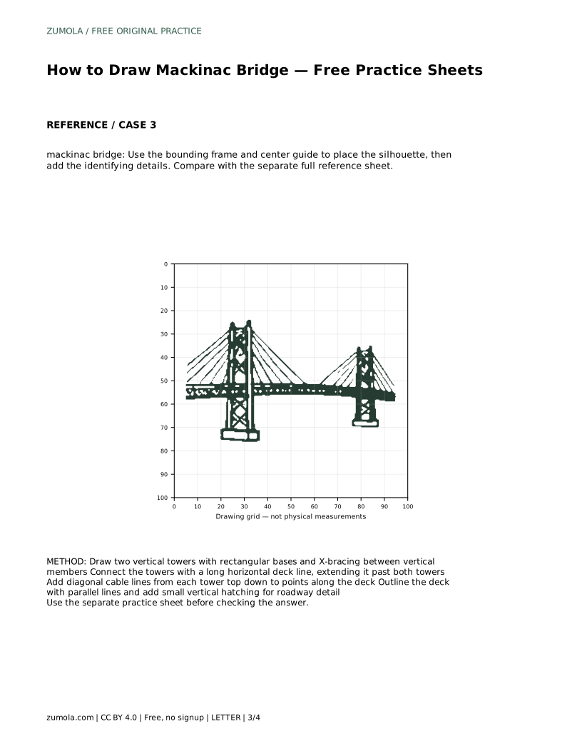
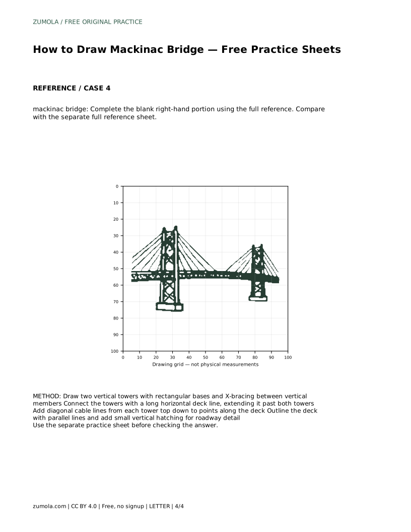
Example solution: preserve Two tall towers with cross-braced lattice structure, Long horizontal deck spanning between and beyond the towers, Diagonal suspension cables radiating from tower tops to the deck. Other drawings can be correct; assess the visible features and proportions rather than pixel-perfect matching. Draw two vertical towers with rectangular bases and X-bracing between vertical members Connect the towers with a long horizontal deck line, extending it past both towers Add diagonal cable lines from each tower top down to points along the deck Outline the deck with parallel lines and add small vertical hatching for roadway detail
They should look like a matched pair, so keep them close in height and width. Small differences are fine, but a large mismatch makes the bridge look unbalanced.
Draw them as straight diagonal lines. Taut cables run directly between the tower top and their deck anchor points, so straight lines read more accurately than curves.
Check that the two braced towers, the long deck extending past them, and the radiating cables are all clearly visible and reasonably proportioned. Several different drawings can all be correct.
All drawing practice · Free coordinate paper
Original resources · CC BY 4.0 · Free for personal and classroom use with attribution.